The wide application of wireless sound reinforcement systems solves the problems of wiring and mobile use in practical projects. The wireless transmission mode has also evolved from the traditional U-segment and V-segment wireless sound reinforcement to today's infrared digital, Bluetooth and wireless digital transmission in the 2.4 GHz band. The use of the traditional analog signal wireless amplifier equipment transmitter will be interfered by the same frequency, adjacent frequency or outside radio waves, and the amplification of the amplified sound will be large, and the high frequency wave radiation will be large. The amplification and feedback will cause certain damage to the human eardrum. s damage. Audio is less likely to be disturbed during transmission of digital signals and has strong anti-interference ability. Digital wireless sound reinforcement system can be widely used in teaching, conference venues, modern office, home life and other fields.
Works on the 2.4 GHz ISM. There are 400 million usable address codes in the frequency band, which can be guaranteed to be used simultaneously in the same place without frequency interference through frequency hopping enquiry technology. The frequency bandwidth of the transmitted signal is greater than the minimum bandwidth required for the transmitted information, and the bandwidth spread is achieved through the extended function, irrelevant to the transmitted information data, and only the transmitter and the receiver know, and the same spreading code is used at the receiving end. Correlated demodulation is performed to despread and recover the transmitted information data. The data is carried by all the frequency hopping points. If the noise does not affect all the frequency hopping points, the information can be repaired. Under certain conditions, multiple systems can coexist in the same frequency range. This article describes the design of a wireless smart frequency hopping digital loudspeaker developed using the ATmega8 MCU and nRF24L01 RF transceivers. Using intelligent frequency hopping addressing technology, the transmitter can be automatically recognized by the receiver more quickly. Any transmitter can be matched to any receiver. After matching, it will automatically lock until the transmitter is turned off or out of radio coverage. The output power is 5 W and the effective distance of transmission and reception is ≤60 m under the straight line transmission condition without obstacles.
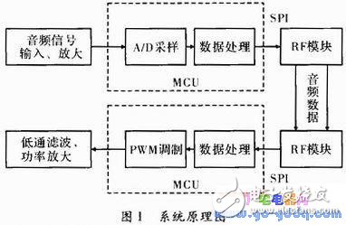
1 System Analysis and DesignThe system consists of an MCU, a transmitting and receiving system. The audio signal is amplified by the front-end signal processing circuit of the transmitting end and sent to the MCU A/D for sampling. The MCU packages the sampled data and sends it through the RF module. The receiving MCU reads the data packet from the RF module and sends it to TIMER1 inside the MCU for PWM modulation, and then outputs it to an external low-pass filter, and finally recovers the corresponding audio signal. The system principle is shown in Figure 1.
1.1 Main Control MCU Module
The MCU selects the AVR family of ATmega8s, which are low power 8-bit CMOS microcontrollers based on an enhanced AVR RISC architecture. Due to its advanced instruction set and single clock cycle instruction execution time, ATmega8's data throughput rate reaches 1 MIPS/MHz, and its performance reaches 16 MIPS at 16 MHz, so the conflict between power consumption and processing speed can be reduced. Operating voltage 2.7 ~ 5.5 V, internal 8-bit 10-bit ADC, SPI serial interface, 16-bit timer with PWM modulation output, 512 Byte EEPROM. Its internal resources can meet the requirements of the transmitter and receiver MCUs
1.2 RF module
The nRF24L01 is a new single-chip RF transceiver that operates in the 2.4 to 2.5 cHz ISM band. Built-in frequency synthesizers, power amplifiers, crystal oscillators, modulators and other functional modules, and incorporates enhanced ShockBurst technology, which output power and communication channels can be configured by the program. Address and CRC check functions can be performed. The nRF24L01 has low power consumption, and operates at 9 mA when transmitting at a power of -6 dBm. At reception, it operates at a current of 12.3 mA. A variety of low-power operation modes make energy-saving design more convenient. The carriers that transmit and receive the signals on both sides change discretely according to a predetermined rule to avoid interference and complete the transmission. In short, frequency hopping FHSS does not suppress interference but tolerate interference. Because the carrier frequency is a jump, it has the ability to resist high frequency and partial bandwidth interference. When the number of frequency jumps is enough and the frequency hopping bandwidth is wide enough, its anti-interference ability is strong. The use of rapid hops in the carrier frequency has the effect of frequency diversity, thus making the system resistant to multipath fading. Using orthogonality of the frequency hopping pattern can constitute a frequency hopping code division multiple access system, share spectrum resources, and have the ability to withstand overload.
1.3 Audio amplification
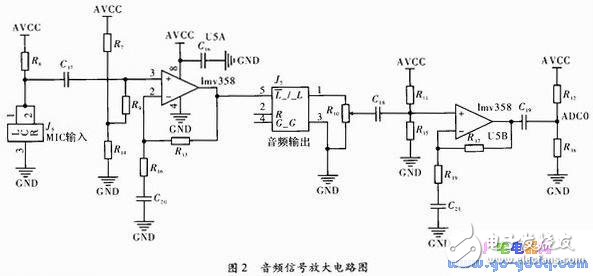
As shown in FIG. 2, the circuits U5A, R8, C17, R7, R14, R9, R16, R13 are responsible for the amplification of the microphone input signal, and the amplification factor is 10 times. Among them R8 provides the direct current bias to the microphone, is coupled to operational amplifier U5A through C17. R7, R14, R9 are used to provide a virtual ground for the op amp. If a 3.5 mm audio signal connector is plugged into J5, subsequent circuitry will disconnect the pre-amplifier to allow switching between MIC sound and external audio input. U5B, R11, R15, R17, R19, C21 are responsible for the input MIC and external audio signal amplification, the magnification is 5 times, the principle is similar to the preamplifier. The op amp uses the LMV358. The LMV358 is a Rail to Rail dual op amp with an operating voltage of 2.7 to 5 V, a gain bandwidth product of 1 MHz, and an operating current of 140 μA. It is suitable for battery operation.
1.4 Power Supply Regulation
LDO uses PAM3101, a series of forward linear regulators featuring low quiescent current and low voltage drop, making it ideal for battery-powered applications. Small size SOT-23 and SOT-89 packages are attractive for portable and launch devices. Thermal shutdown and current limiting prevent the device from failing under extreme operating conditions.
Customized Laboratory Testing Instruments
Wuxi Lerin New Energy Technology Co.,Ltd. , https://www.lerin-tech.com