The current transmitter can directly convert the AC current or DC current of the main circuit under test into DC 4~20mA (converting DC1~5V through 250Ω resistor or converting DC2~10V through 500Ω resistor) to the constant current loop standard signal. Delivered to a receiving device (computer or display instrument).
The current transmitter is divided into two types: DC current transmitter and AC current transmitter. The AC current transmitter is an instrument that can convert the measured AC current into a linear proportional output DC voltage or DC current. The products are widely used in electrical equipment of electric power, post and telecommunications, petroleum, coal, metallurgy, railway, municipal and other departments. , automatic control and scheduling system. The AC current and voltage transmitters have a single-way, three-way combined structure, which is characterized by:
1. High accuracy (typical: 0.2%, preferably 0.05%);
2. The entire range has a very high linearity;
3. High degree of integration, simple structure, excellent temperature characteristics and long-term working stability, so that the transmitter is free of regular calibration.

*Executive standard: GB/T13850-1998, IEC688:1992
*Input range: 0~10A can be selected as 0~1A, 0~5A, etc.
*Accuracy level: ≤0.2%.FS
* Temperature characteristics: ≤100PPM/°C (0~50°C)
* Machine power consumption: ≤1.0VA
*Work stability: annual change "0.2%
*Isolation withstand voltage: AC2.0KV/min*1mA between input/output/outer casing
*Insulation resistance: ≥20MΩ (DC500V)
* Shock voltage: 5KV (peak), 1.2/50uS
* Response time: ≤300mS
*Overload capability: 2 times continuous current, 30 times 1 second
*Working environment: -10 °C ~ 50 °C, 20%~90% without condensation
* Storage environment: -40 ° C ~ 70 ° C, 20% ~ 95% without condensation
Current transmitter working principleThe XTR115 is packaged in an SO-8 miniaturized package. The internal circuit block diagram and basic application circuit are shown in Figure 1. U+ is the power supply terminal and is connected to the loop power supply. UREF is the 2.5V reference output. II terminates the input current. IRET is the return of the reference output current and the regulator output current and can be used as a common ground for the input circuit. OUT is a 4~20mA current output. UREG is the output of the +5V regulator. The B and E terminals are the interfaces of the external power tubes, which are respectively connected to the base (B) and the emitter (E) of the power tube. The collector (C) of the power tube is connected to the U+ terminal. The chip mainly includes input amplifier (A), resistor network, output transistor (VT1), 2.5V reference and +5V regulator. RLIM is an internal current limiting resistor. The peripheral components mainly include input resistance (RI), power tube (VT2), loop power (Us) and load resistor (RL). The input voltage UI is first converted into input current II by RI, and then amplified by XTR115 to output a current signal of 4~20 mA from the OUT terminal. In order to reduce the offset voltage and the drift of the input amplifier, UI "0.5V ​​is required.
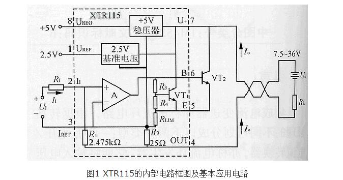
It should be pointed out that the XTR115 can only be equipped with an NPN power tube and cannot be equipped with a MOS field effect power tube. The external power tube should meet the voltage and current requirements of the XTR115. The power tube must also be equipped with a suitable heat sink.
The role of the current transmitterThe current transmitter is divided into two types: DC current transmitter and AC current transmitter.
The AC current transmitter is an instrument that can convert the measured AC current into a linear proportional output DC voltage or DC current. The products are widely used in electrical equipment of electric power, post and telecommunications, petroleum, coal, metallurgy, railway, municipal and other departments. , automatic control and scheduling system. The AC current and voltage transmitters have a single-way, three-way combination structure.
The DC current transmitter converts the measured signal into a voltage, which is directly converted into a voltage that is in a perfectly linear relationship with the measured signal and completely isolated by the HCNR200/201 linear optical coupler, and then is subjected to constant voltage (flow) to the output. The principle is very simple, the circuit design is refined, the reliability is high, and the installation is convenient.
The current transmitter can directly convert the AC current in the main circuit under test into DC 4~20mA which is linearly proportionally outputted (converted to DC 1~5V through 250Ω resistor or 2~10V through 500Ω resistor) constant current loop standard The signal is continuously delivered to the receiving device (computer or display instrument).
The current transmitter is insulated and isolated from the primary and secondary sides. It has two-wire and three-wire output wiring. The three-wire transmitter has an auxiliary working power supply +24V positive terminal, negative terminal and signal output terminal.
The two-wire transmitter is the positive terminal of the +24V termination transmitter of the auxiliary working power supply. The negative terminal of the power supply is connected to the negative terminal of the transmitter through a sampling resistor or ammeter.
In many applications controlled by a single-chip microcomputer, the current transmitter must use a transmitter to convert a signal that cannot be directly measured by the single-chip microcomputer into an electrical analog signal that can be processed by the single-chip microcomputer, such as a current transmitter, a pressure transmitter, and a temperature transmitter. , flow transmitters, etc. Most of the early transmitters were voltage output type, which converted the measurement signal to 0-5V voltage output. This is the direct output of the op amp. The signal power is 0.05W. The digital signal is converted by the analog/digital conversion circuit for reading and controlling by the MCU. .
The lower water in the liquid level sensor and the condensed water of the upper steam are sent to the sides of the bellows of the transmitter through the instrument tube, and the differential pressure on both sides of the bellows drives the mechanical amplifying device to indicate the water level by a pointer. meter. Of course, it is also possible to convert the electrical analog quantity into a digital quantity. The above just conceptually illustrates the difference between a sensor and a transmitter. The two-wire current output type current transmitter has been widely used due to its extremely high anti-interference ability.
Current circuit transmitter circuit diagram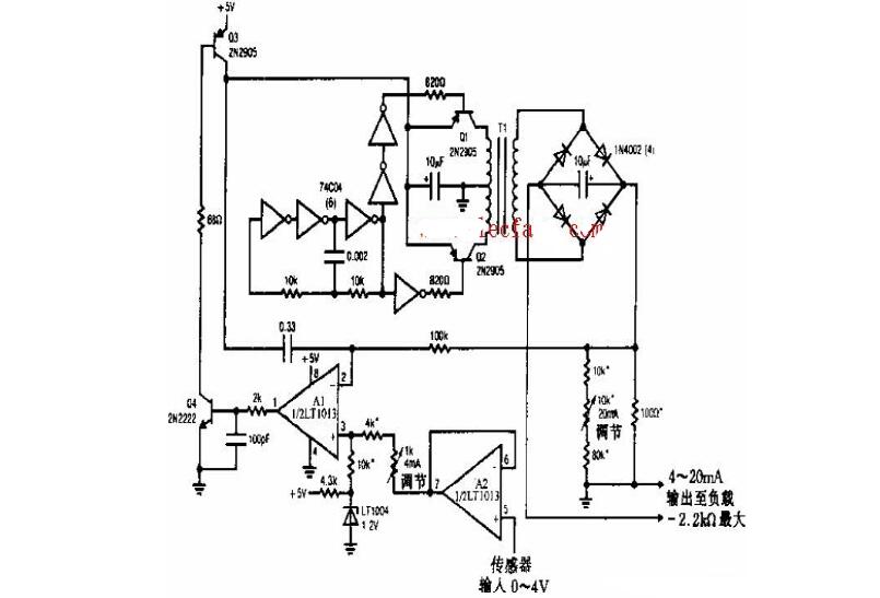
Note: The accuracy of the circuit transmitter is 12 bits. 1% thin film resistor, T1 is PICO-31080. See LT1013 for instructions.
Current transmitter considerations* Pay attention to the auxiliary power information on the product label. The auxiliary power level and polarity of the transmitter cannot be connected incorrectly, otherwise the transmitter will be damaged.
*Transmitter is an integrated structure, non-removable, and should avoid collision and drop;
*When the transmitter is used in an environment with strong magnetic interference, please pay attention to the shielding of the input line, and the output signal should be as short as possible. For centralized installation, the minimum installation interval should not be less than 10mm;
* There is no lightning protection circuit inside the series of transmitters. When the transmitter input and output feeders are exposed to outdoor harsh weather conditions, lightning protection measures should be taken;
* This product is packaged in a flame-retardant ABS plastic case. The ultimate endurance temperature of the case is +85 °C. When it is baked at high temperature, it will be deformed and affect the performance of the product. Do not use or store the product near the heat source. Do not put the product into a high temperature box for baking;
* Do not damage or modify the product's label, logo, do not disassemble or modify the transmitter, otherwise the company will no longer provide "three guarantees" (including replacement, return, repair) service.
Power 90W ,output voltage 15-24V, output current Max 6A, 10 dc tips.
We can meet your specific requirement of the products, like label design. The plug type is US/UK/AU/EU. The material of this product is PC+ABS. All condition of our product is 100% brand new. OEM and ODM are available in our company, and you deserve the best service. You can send more details of this product, so that we can offer best service to you!
90W Desktop Adapter,90W Desktop Power Supply,90W Desktop Power Cord , 90W Desktop Power Adapter
Shenzhen Waweis Technology Co., Ltd. , https://www.laptopsasdapter.com