The working mode of the serial port is 0. The input/output mode of the shift register. After the mode 0 transmits or receives the 8-bit data, the hardware sends the interrupt flag TI or the interrupt flag RI.
1. Mode 0 send
Serial data is output from the RXD pin and the TXD pin outputs a shift pulse. When the CPU writes data to the transmit register (SBUF), it immediately starts transmitting, and outputs 8-bit data from RXD at a fixed baud rate of fosc/12. The low bit is first, the high bit is after, and the highest bit (D7 bit) is digitally shifted out. After that, stop sending data and shift clock pulses.
MOV SCON, #10H ; Serial port mode 0
MOV A, SBUF ; Receive data
JNB RI, $ ; Waiting for data to be received
2. Mode 0 receiving
Before mode 0 is received, be sure to set REN=1 first to allow data to be received. At this time, RXD is the serial data input terminal, and TXD is still the synchronous pulse shift output terminal. When RI=0 and REN=1 are satisfied at the same time, a receiving process is initiated. The receiver receives the data input at the TXD terminal at a fixed baud rate of fosc/12. When the 8th bit of data is received, the data is shifted into the receive register, and the RI is set by the hardware to request an interrupt from the CPU.
MOV SCON, #00H ; Serial port mode 0
MOV SBUF, A ; Send data out
JNB TI, $ ; Waiting for data to be sent
Working mode 0 is generally used for the expansion of parallel input and output ports, as shown in Figure 1.
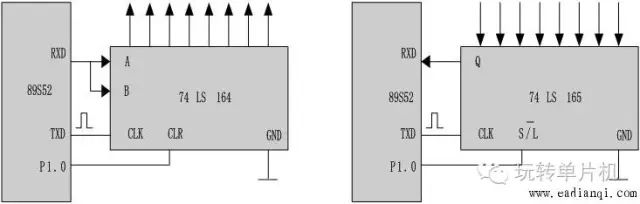
Figure 1 Application of mode 0
Second, mode 1: 8-bit UART mode
When SM0=0, SM1=l, the serial port selects mode 1, and the MCU works in 8-bit data asynchronous communication mode (UART). In mode 1, one frame of information is transmitted as 10 bits, that is, a 1-bit start bit (0), an 8-bit data bit (lower bit first), and a 1-bit stop bit (1). The data format of mode 1 is shown in Figure 2.
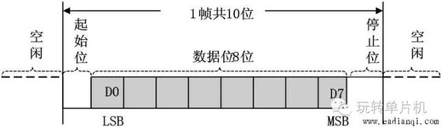
Figure 2 Data format of mode 1
1. Mode 1 send
When the CPU executes MOV A, the SBUF instruction writes data to the transmit buffer SBUF to initiate transmission. The start bit is first output to TXD, and then the output bit of the shift register is sent to TXD. The first shift pulse (SHIFT) is then issued, shifting the data one bit to the right and adding 0 to the left. After that, the data will be sent bit by bit from the TXD end, and the left side will be continuously added with 0. After transmitting one frame of data, the TI is set by hardware.
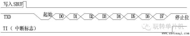
Figure 3 Mode 1 Send
2. Mode 1 reception
After REN=1 and receiving the start bit, under the control of the shift pulse, the received data is shifted into the receive buffer register (SBUF). After the stop bit arrives, the stop bit is sent to RB8 and set. RI, the CPU is notified to receive a character.
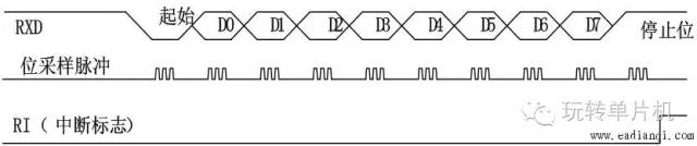
Figure 4 Mode 1 Receive
Third, mode 2 and mode 3: 9-bit data asynchronous communication mode
When SM0=1, SM1=0, the serial port selects mode 2; when SM1=1, SM0=1, the serial port selects mode 3. Mode 2 and Mode 3 work similarly, defined as a 9-bit asynchronous communication interface, transmitting (through TXD) and receiving (via RXD) one frame of information is 11 bits, 1 bit start bit (0), 8 bits of data Bit (lower bit first), 1 bit programmable bit (ie 9th bit data) and 1 bit stop bit (1). Its data format is shown in Figure 5.

Figure 5 Data format for modes 2 and 3
The only difference between mode 2 and mode 3 is that the baud rate of mode 2 is fixed, and the baud rate of mode 3 is variable.
1. Mode 2 and Mode 3 send
When the CPU executes an instruction to write a data to SUBF, the transmitter is started to transmit. Put the start bit (0) on the TXD end. After one bit of time, the data is sent to the TXD terminal by the shift register. The first shift pulse appears through the first bit data. When the contents of TB8 are moved to the output position of the bit register, the left bit is the stop bit "1", and all the left bits are all "0". After this state is detected by the zero detector, the transmitting controller is notified to make the last shift, and then TI=1 is set to request an interrupt. The sending process is shown in Figure 6.

Figure 6 Mode 2 and 3 transmission
2. Mode 2 and Mode 3 receiving
When receiving, the data is shifted from the right into the input shift register, and when the start bit 0 is shifted to the leftmost position, the control circuit performs the last shift. When RI=0 and SM2=0 (or the received ninth bit data is 1), the received data is loaded into the receive buffers SBUF and RB8 (the ninth bit of the received data), and RI=1, The CPU requests an interrupt. If the condition is not met, the data is lost and the RI is not asserted, continuing to search for a negative transition on the RXD pin. The process of receiving is shown in Figure 7.
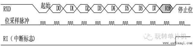
Figure 7 Reception of Modes 2 and 3
Fourth, the calculation of the baud rate
The baud rate reflects the rate at which the serial port transfers data, depending on the oscillation frequency, the SCON bit of the PCON register, and the timer setting. In serial communication, the data transfer rate (baud rate) of both senders and receivers must follow certain conventions. Among the four operating modes of the AT89S52 serial port, the baud rates of modes 0 and 2 are fixed, while the baud rates of modes 1 and 3 are variable and controlled by the overflow rate of the timer.
Mode 0 is a fixed baud rate: baud rate = fosc/12
Mode 2 can choose two baud rates: baud rate = (2SMOD / 64) × fosc
When SMOD=1, the baud rate = fosc/32;
When SMOD=0, the baud rate = fosc/64.
Modes 1, 3 are variable baud rates, and T1 is used as the baud rate generator.
Baud rate = (2SMOD / 32) × T1 overflow rate, T1 overflow rate is the reciprocal of the time required for T1 to overflow once.
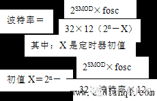
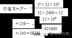
For example: Calculate the baud rate. It is required to operate in mode 2 with T1 to generate a baud rate of 2400, known as crystal frequency = 12 MHz.
Solution: Find the initial value of T1:
Common baud rate and T1 initial value can refer to Table 6-2 in the textbook. Five, multi-machine communication
In a distributed distribution system, one host and multiple slaves are often used. The information sent by the host can be received by each slave, and the information of each slave can only be received by the host, and the slave and the slave cannot communicate with each other directly.
Figure 8 is a schematic diagram of multi-machine communication connection. The left side of the system is the host, and the rest are slaves from 1 to n, and the number of each slave in the system is guaranteed to be unique.
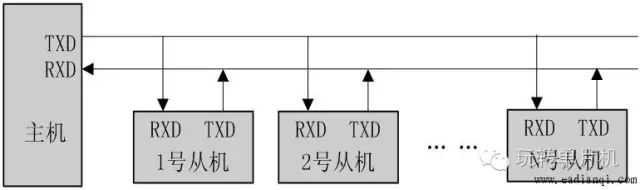
Figure 8 Multi-communication diagram
Ac Motor,220V Servo Motor,Ac Motor With Speed Controller,Remote Motor With Speed Controller
NingBo BeiLun HengFeng Electromotor Manufacture Co.,Ltd. , https://www.hengfengmotor.com