This article brings you the design of two stepping motor control systems for 89C51 single-chip microcomputer.
Design of Stepping Motor Control System for 89C51 Single Chip MicrocomputerThe whole system diagram is shown in Figure 1. The system uses an external interrupt mode. The p0 port is used as the input part of the signal, the p1 port is the LED display part, and the p2 port is the driving part of the motor.
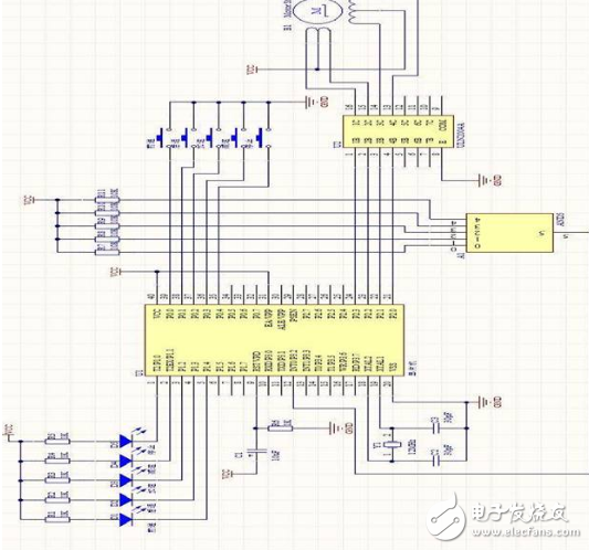
Figure 1 System diagram
Power sectionUsing the LM7812 and LM7805 chips to get 12V and 5V voltage, their application should pay attention to the following points:
(1) The input/output differential pressure should not be too large, if the conversion efficiency is too fast, the conversion efficiency is rapidly reduced, and it is easy to break down and damage;
(2) The output current should not be too large, and 1.5A is its limit value. The output of the high current, the size of the heat sink should be large enough, otherwise it will lead to high temperature protection or thermal breakdown;
(3) The input and output pressure difference should not be too small, and the size efficiency is very poor. The 12V voltage supplies power to the stepper motor, and the 5V voltage supplies power to the microcontroller. As shown in Figure 2 and Figure 3, respectively.
(1) generate 12V voltage to power the stepper motor
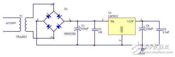
Figure 2 12V circuit part
(2) generate 5V voltage to power the microcontroller
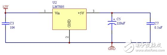
Figure 3 5V circuit part
Button partThis design selects the P0 port of the single-chip microcomputer to control the input of the signal, so the key switch is connected with the P0 port. When the switch S1 is pressed, it is equivalent to giving the P0.0 port a low level; when the switch S2 is pressed When it is equivalent to a low level to the P0.1 port; when the switch S3 is pressed, it is equivalent to a low level to the P0.2 port; when the switch S4 is pressed, it is equivalent to a low power to the P0.3 port. Flat; when the switch S5 is pressed, it is equivalent to giving the P0.4 port a low level. Then through the microcontroller to carry out the corresponding operation. As shown in Figure 4.
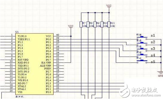
Figure 4 button part circuit
Drive sectionThis circuit is the driving part of the stepper motor. I chose the ULN2004 chip to drive it. The ULN2004 series is a high-voltage, high-current Darlington tube driver with 7 NPN Darlington tubes. As shown in Figure 5.
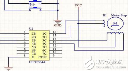
Figure 5 driving part of the circuit
Status indication sectionThe status indication uses the P1 port to control the display of the LED. If the corresponding port is low, the corresponding LED will illuminate and use it to indicate the state of the stepper motor.
Clock part
The clock circuit is the heart of the computer. It controls the working rhythm of the computer. It can increase the speed of the CPU by increasing the clock frequency. The crystal oscillator used in this design is 12MHz. As shown in Figure 6.
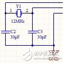
Figure 6 clock part circuit
Liquid Crystal Display,Lcd Screen Displays,Calculator Lcd Display,Lcd Display For Car Bluetooth
Dongguan Yijia Optoelectronics Co., Ltd. , https://www.everbestlcdlcms.com