Temperature and Thermocouple Overview <br> Temperature is the measure of the average kinetic energy of a particle in an object's sample. The standard unit is “degreeâ€. The temperature can be measured by different methods, and the cost and accuracy of the measurement are different. A thermocouple is one of the most common sensors for measuring temperature because thermocouples are relatively inexpensive and accurate, and their measurement ranges are relatively wide.
Whenever two different metals come in contact, the contact point produces a lower no-load voltage as a function of temperature, which is the thermoelectric effect. This temperature differential voltage is the Seebeck voltage, named after physicist Thomas Seebeck, who discovered the phenomenon in 1821. This voltage is non-linear with respect to temperature, but can be approximated as linear for a small range of varying temperatures, or:
![]() (1)
(1)
In the formula, ?V is the voltage change, S is the Seebeck coefficient, and ?T is the temperature change.
There are many types of thermocouples and they are all stipulated by the American National Standards Institute (ANSI) convention, and their composition is indicated by larger letters. For example, a J-type thermocouple consists of an iron conductor and a copper-nickel alloy conductor. Other types of thermocouples include B, E, K, N, R, S, and T.
How to measure a thermocouple
background knowledge
To better understand how to make thermocouple measurements, you must first understand how thermocouples work. The first part of this document will explain the basic principles of thermocouples, and later sections will explain how to implement the connection between the thermocouple and the instrument and how to measure the temperature.
The thermocouple Seebeck voltage is directly connected to the measurement system and connected to the measurement system will generate an additional temperature difference circuit, so it cannot be measured by simply connecting it to a voltmeter or other measurement system.

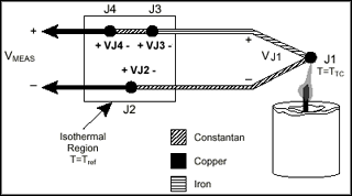
Figure 1. Type J thermocouple
As shown in Figure 1, a J-type thermocouple was used in the circuit to measure the candle temperature. Two thermocouple wires are connected to the copper connection terminals of the data acquisition device. Note that there are three metal connections in this circuit - J1, J2, and J3. J1 is a thermocouple measurement point that produces a Seebeck voltage that is proportional to the temperature of the candle. In addition, each of J2 and J3 has its own Seebeck coefficient, and a temperature difference voltage proportional to the temperature is generated at the data acquisition terminal, which is called the cold junction voltage. In order to determine the voltage component of J1, it is necessary to know the temperature of the J2 and J3 junctions, and to know the relationship between the junction voltage and the temperature. In this way, the J1 junction voltage can be obtained by subtracting the J2 and J3 parasitic junction voltage components from the measured voltage.
Thermocouples require a specific temperature reference to compensate for the error produced by the cold junction. The most commonly specified method is to use a temperature sensor that can read directly to measure the reference junction temperature, minus the parasitic terminal voltage component. This method of processing is called cold-junction compensation. Some thermocouple characteristics can be used to simplify the calculation of cold-junction compensation.
By using the thermocouple law of the metal transition layer and other assumptions, we can see that the measurement of the voltage data acquisition system only depends on the thermocouple type, the measurement terminal voltage, and the cold junction temperature. The measured voltage is independent of the voltage components of the measuring leads and the cold junctions J2, J3.

Figure 2. The Thermocouple Law of Metal Transition Layers
Consider the circuit in Figure 3. This circuit is similar to the circuit described earlier in Figure 1, but a small length of copper-nickel alloy wire is inserted before the J3 contact. All joints are at the same temperature. Assuming that the junction temperatures of J3 and J4 are the same, the thermocouple law of the metal transition layer illustrates that the circuit in FIG. 3 is the same in electrical theory as the circuit in FIG. Therefore, any results measured by the circuit of Figure 3 apply to the circuit shown in Figure 1.

Figure 3. Inserting an additional wire in an isothermal environment
In Figure 3, J2 and J4 junctions are of the same type (copper-nickel alloy); because both are in an isothermal environment, J2 and J4 are at the same temperature. Because of the direction of the current in the circuit, a positive Seebeck voltage is generated at J4 and a negative Seebeck voltage is generated at J2. Therefore, the contacts counteract each other's influence and the total amount of measurement voltage is zero. Both J1 and J3 contacts are iron-copper-nickel alloy contacts. But their temperature may be different because they may not be in an isothermal environment. Because they are in different temperature environments, J1 and J3 junctions can produce Seebeck voltage, but the size is different. To compensate for the cold junction J3, its temperature is measured and its applied voltage is subtracted from the thermocouple measurement.
Using the VJx (Ty) symbol to represent the voltage produced by the Jx contact at Ty temperature, the general thermocouple problem is simplified to the following equation:
VMEAS = VJ1(TTC) + VJ3(Tref ) (2)
In the formula, VMEAS represents the voltage value measured by the data acquisition system, TTC represents the temperature of the J1 junction thermocouple, and Tref represents the temperature of the reference end.
Note that in equation (2), VJx(Ty) represents the voltage generated under the Ty temperature environment for a certain reference temperature. As long as VJ1 and VJ3 are temperature functions related to the same reference temperature, Equation 2 holds. For example, the NIST thermocouple reference table as described above is generated with the reference end kept at 0 degrees Celsius.
Since J3 and J1 are of the same type but generate relative voltages, VJ3(Tref) = -VJ1(Tref). Since VJ1 is a voltage generated in the thermocouple type test state, the voltage can be renamed to VTC. Therefore, Equation 2 can be rewritten as:
VMEAS = VTC (TTC) - VTC (Tref ) (3)
Therefore, by measuring VMEAS and Tref to know the relationship between thermocouple voltage and temperature, the temperature at the thermocouple measurement end can be determined.
There are two technologies that implement cold junction compensation - hardware compensation and software compensation. Both technologies require the use of a direct reading sensor to get the reference temperature. The direct-reading sensor has an input that is determined only by the temperature of the measuring point. Semiconductor sensors, thermistors, and RTDs are commonly used instruments for measuring the temperature at the reference end.
Using hardware compensation, a variable voltage source can be inserted into the circuit to remove the parasitic temperature difference voltage. The variable voltage source generates a compensation voltage based on the ambient temperature and is thus added to the correction voltage to cancel the unwanted temperature difference signal. When these spurious signals have been removed, the only signal measured by the data acquisition system is the voltage measured from the thermocouple measurement side. With hardware compensation, the temperature of the data acquisition system terminal is irrelevant because the parasitic thermocouple voltage has been removed. The main disadvantage of hardware compensation is that each thermocouple must have a separate compensation circuit that can additionally modify the compensation voltage, which will greatly increase the cost of the circuit. Under normal circumstances, hardware compensation is not as accurate as software compensation.
Or you can choose to use the software for cold-junction compensation. After using the direct-reading sensor to measure the reference temperature, the software can add a suitable voltage value to the measured voltage to eliminate the influence of the cold-junction voltage. Memories in (3) indicate that the measured voltage VMEAS is equal to the (thermocouple) voltage difference between the measurement terminal contact and the cold junction.
The thermocouple output voltage is highly nonlinear. The Seebeck coefficient may vary due to three or more factors in the operating temperature range of some thermocouples. Therefore, you must use a polynomial to simulate the voltage vs. temperature curve in a thermocouple or use a look-up table method.
Connect the thermocouple to the instrument
This section uses the NI cDAQ-9172 backplane and the NI 9211 C Series thermocouple module as an example. A similar procedure is suitable for connecting thermocouples to different instruments. Required equipment:
DAQ-9172 8-Slot Hi-Speed ​​USB Backplane for NI CompactDAQ
NI 9211 Quad, 14Sa/s, 24-Bit, 80mV Thermocouple Input Module
J type thermocouple
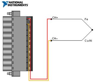
The NI 9211 has a 10-junction, detachable screw terminal connector that provides connections for four thermocouple input channels. Each channel has a connection point for the positive thermocouple connection, TC+, and a connection point to the negative electrode, TC-. The NI 9211 also has a common wiring point, COM. Usually this port is internally connected to the reference ground of the module.

Figure 4 connection diagram
Check Your Measurement Results: NI LabVIEW
Now that the thermocouple is connected to the test equipment, you can use LabVIEW graphical programming software to transfer the data to a computer for visualization and analysis.
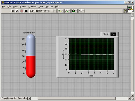
Figure 5 shows an example of displaying measured temperature data in the LabVIEW programming environment.

Figure 5. LabVIEW Front Panel Showing Temperature Data
Excerpt from: NI "General Measurement Guide"
Floor brackets are an essential component of cable tray systems. They are used to support cable trays on the floor, providing a secure and stable platform for cable management. In this article, we will take a closer look at floor brackets of cable tray systems.
What are floor brackets?
Floor brackets are metal structures that are designed to support and secure cable trays on the floor. They are typically made of steel or aluminum and come in various sizes and shapes to accommodate different cable tray configurations. Floor brackets are attached to the floor using bolts or screws and provide a stable base for cable trays to rest on.
Types of floor brackets
There are several types of floor brackets available for cable tray systems. The most common types include:
1. L-shaped brackets: These brackets are shaped like an L and are used to support cable trays that run parallel to the wall. They are typically attached to the floor using two bolts or screws.
2. U-shaped brackets: These brackets are shaped like a U and are used to support cable trays that run perpendicular to the wall. They are typically attached to the floor using four bolts or screws.
3. Z-shaped brackets: These brackets are shaped like a Z and are used to support cable trays that run at an angle. They are typically attached to the floor using four bolts or screws.
4. T-shaped brackets: These brackets are shaped like a T and are used to support cable trays that intersect with other cable trays. They are typically attached to the floor using four bolts or screws.
Floor Brackets Of Cable Tray,Adjustable Floor Brackets,Standard Floor Brackets,Heavy-Duty Floor Brackets
Rayhot Technology Group Co.,Ltd , https://www.cnrayhot.com