A serial interface is a device that converts parallel data characters received from the CPU into a continuous serial data stream and converts the accepted serial data stream into parallel data characters to the CPU. Circuits that generally accomplish this function are called serial interface circuits.
This text mainly introduces the working principle of the serial port on the one-chip computer and how to set up the serial port through the procedure, and realize and communicate with PC according to the example given.
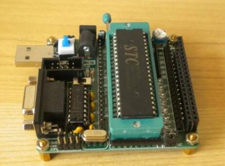
The 51 microcontroller has a full duplex serial interface. What is a full duplex serial port? In general, only one can receive or send can be called simplex serial; can receive and send, but can not be called at the same time as the half-duplex; can receive and send at the same time the serial port is called full-duplex Serial port. Serial communication refers to the transmission of data one by one in a sequential manner. Its outstanding advantage is that it requires only one transmission line, which can greatly reduce hardware costs and is suitable for long-distance communication. The disadvantage is the low transmission speed.
As before, first of all, let us understand the serial port related to the microcontroller.
SBUF register: it is two physical and independent receive and send buffers, which can send and receive data at the same time. The instruction can read and write SBUF to distinguish whether it is the operation of the receive buffer or the send buffer. To control the external two independent transmit and receive signal lines RXD (P3.0), TXD (P3.1), while sending and receiving data to achieve full duplex.
Serial port control register SCON (see Table 1).

The meaning of each person in the table (from left to right from high to low) is as follows.
SM0 and SM1: serial port operation mode control bits, the definition of which is shown in Table 2.

Among them, fOSC is the clock frequency of the one-chip computer; The baud rate refers to the number of bits that the serial port sends (or receives) every second.
SM2: Multi-machine communication control bit. This is only for multi-machine communication of Mode 2 and Mode 3. Among them, the sender SM2 = 1 (program control settings are required). The serial port of the receiver works in mode 2 or 3. When SM2=1, the first 8 bits received are sent to SBUF only when the 9th bit (RB8) is received is 1, and RI is set. An interrupt request is issued to initiate a serial receive interrupt, otherwise the received data is discarded. When SM2 = 0, regardless of whether the bit data is 0 or 1, data is sent to SBUF, and RI is set to issue an interrupt request. When working in mode 0, SM2 must be 0.
REN: serial receive enable bit: REN = 0, disable reception; REN = 1, allow receive.
TB8: In Modes 2 and 3, TB8 is the 9th bit data to be sent by the transmitter. In multi-machine communication, it represents the transmitted address or data, TB8=0 is data, and TB8=1 is the address.
RB8: In Modes 2 and 3, RB8 is the 9th bit data received by the receiver. This data comes from the TB8 of the transmitter and identifies the characteristics of the received data.
TI: Serial port sends an interrupt request flag. When the CPU sends a serial data, the SBUF register is empty and the hardware sets TI to 1 and requests an interrupt. After the CPU responds to the interrupt, TI is cleared by software.
RI: Serial port receives interrupt request flag. When the serial port receives a frame of serial data, the SBUF register is full and the hardware sets RI to request an interrupt. The RI is cleared in software after the CPU responds to the interrupt.
Power Control Register PCON (see Table 3).

The meaning of each person in the table (from left to right from high to low) is as follows.
SMOD: baud rate doubled. SMOD=1, when the serial port works in modes 1, 2, and 3, the baud rate doubles. SMOD=0, the baud rate does not change.
GF1, GF0: Universal flag.
PD (PCON.1): Power-down mode bit. When PD=1, the power-down mode is entered.
IDL (PCON.0): Standby mode bit. When IDL=1, enter standby mode.
In addition, the registers associated with the serial port include the timer-related registers and interrupt registers described in the previous article. The timer register is used to set the baud rate. The ES bit in the Interrupt Enable Register IE is also used as the serial I/O interrupt enable bit. Serial I/O interrupts are enabled when ES = 1, and serial I/O interrupts are disabled when ES = 0. The PS bit of the interrupt priority register IP is used as the serial I/O interrupt priority control bit. When PS=1, set high priority; when PS=0, set low priority.
Baud rate calculation: After understanding the serial port related registers, we can draw some conclusions about its communication baud rate:
1 The baud rate for Mode 0 and Mode 2 is fixed.
In mode 0, the baud rate is 1/12 of the clock frequency, ie, fOSC/12, fixed.
In Mode 2, the baud rate depends on the SMOD value in PCON, ie the baud rate is:

When SMOD=0, the baud rate is fosc/64; when SMOD=1, the baud rate is fosc/32.
2 The baud rate of Mode 1 and Mode 3 is variable and is determined by the overflow rate of Timer1.

When the timer T1 is used as a baud rate generator, an automatic reloading operation mode 2 is usually selected as the timing initial value (Note: Do not confuse the timer operation mode with the serial port operation mode). Its counting structure is 8 bits. Assume that the initial counting value is Count, and the machine cycle of the MCU is T, then the timing time is (256 ? Count)*T. The number of overflows that occur within 1 s (ie, the overflow rate) can be expressed by equation (1):

The formula for calculating the baud rate is shown by formula (2):

In practical applications, the baud rate is usually determined first, and then the initial value of T1 is calculated according to the baud rate. Therefore, formula (2) can also be written as:

The circuit shown in Figure 1 will be described in detail below.
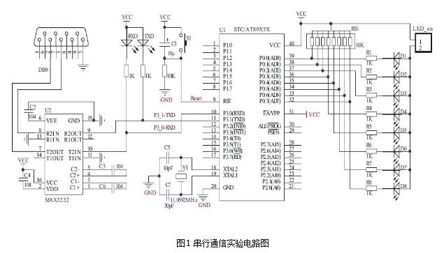
The first part of the minimum system part (clock circuit, reset circuit, etc.) has already been mentioned and will not be described here. We focus on understanding the RS-232 interface circuit that communicates with the computer. It can be seen that in the circuit diagram, there are two status indicators TXD and RXD receive and send, in addition to a chip called MAX3232, then it is used to achieve what? First of all, we must know that the serial port on the computer is a serial interface with RS-232 standard, while the RS-232 standard defines its electrical characteristics: the range of the high level “1†signal voltage is -15V~-3V, low Level "0"
The signal voltage range is +3V~+15V. Some readers may ask, why does it have such electrical characteristics? This is because the high and low levels are represented by the opposite voltage, and the voltage difference of at least 6V is very good to improve the reliability of data transmission. Because the pin level of the one-chip computer is TTL, when the one-chip computer communicates with the serial port of RS-232 standard, the problem that needs to solve is the level shifting first. In general, you can choose some professional integrated circuit chips, such as the MAX3232 in the figure. The MAX3232 chip integrates a voltage multiplication circuit. The single-supply power supply completes the level conversion, and the operating voltage is wide. The 3V to 5.5V can work normally. Its typical application is shown in the figure, and its peripheral connected capacitance has an effect on the transmission rate, which is 0.1μF in the test kit.
It is worth mentioning that the MAX3232 chip has two pairs of level-conversion circuits. In the figure, only one path is used. Therefore, another path is wasted. In some cases, two paths can be connected in parallel to obtain strong drive anti-interference ability. In addition, we need to understand the pin structure of the DB-9 RS-232 connected to the computer in the figure (see Figure 2).
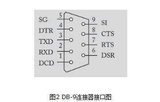
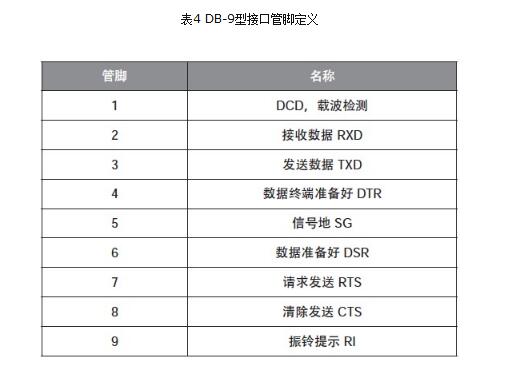
Its pins are defined as follows (see Table 4).
This tutorial design example program is as follows:
#include "AT89X52.h" (1)
Void Init_Com(void) ( 2)
{
TMOD = 0x20; (3)
PCON = 0x00; (4)
SCON = 0x50; (5)
TH1 = 0xE8; (6)
TL1 = 0xE8; (7)
TR1 = 1; (8)
}
Void main(void) ( 9)
{
Unsigned char dat; (10)
Init_Com(); ( 11)
While(1) ( 12)
Detailed description of the program:
(1) The header file contains.
(2) declare the serial initialization procedure.
(3) Set timer 1 to work in mode 2 and automatically load the initial value (see the second lecture).
(4) The SMOD bit is cleared and the baud rate is not doubled.
(5) The serial port operates in Mode 1 and allows reception.
(6) Timer 1 high 8 bits initial value. The baud rate is 1200b/s (7) Timer 1 low 8-bit initial value.
(8) Start the timer.
(9) The main function.
(10) Define a character variable.
(11) Initialize the serial port.
(12) The endless loop.
(13) If data is received.
(14) Assign the received data to the previously defined variable.
(15) Output the received value to port P0.
(16) The reception flag is cleared to 0 and ready to be received again.
(17) Send the received data again.
(18) Whether the inquiry was sent or not.
(19) Clear the send flag to 0.
Fourth, debugging points and experimental phenomenaConnect the hardware and generate the program by cold start. After the hex file is downloaded to the SCM, open the serial debugging assistant software, set the baud rate to 1200, reset the SCM, and then send the data to the SCM through the serial debugging assistant (see Figure 3). You can observe the data sent in the receiving window. In addition, the serial communication indicator on the circuit board will flash, and the LED connected to port P0 will flash the received data.
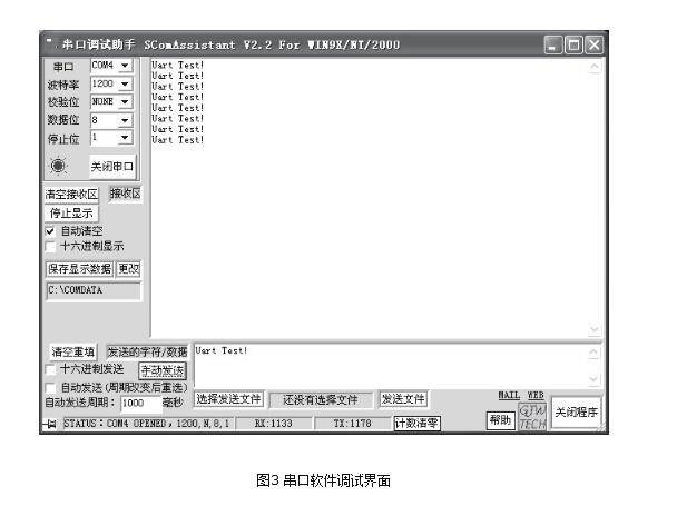
In addition, when the serial debugging assistant software is used, it should be noted that if the MCU development board adopts the serial port download and the serial debugging assistant uses the same serial port, then the serial port software cannot be downloaded to the MCU at the same time. If you need to download, please click " Turn off the serial port. When sending an experiment, note that if hexadecimal is selected, hexadecimal values ​​of digits or letters are sent. For example, if you send "0", the actual received value should be 0x00. If you do not select it, the default message is sent. The ASCII code value, "0" is transmitted at this time, the actual reception should be 0x30, this can be indicated by observing the corresponding LED on the board P0 port.
V. SummaryThis lecture introduces the principle of serial communication of the single-chip microcomputer and gives examples. Through this lecture, the reader can understand and master the principle and application flow of serial communication of the 51 single-chip microcomputer. Using serial communication, the single-chip microcomputer can be connected with a computer, or can be connected with a single-chip microcomputer. One-chip computer mutual communication networking, etc., in a very wide range of practical engineering applications. From a learning point of view, skilled use of the serial port to display related information in the SCM system on the computer can be intuitive and convenient for debugging and development.
Product categories of Disc Stylus Pen, We are the specialized manufacturer of Stylus Pen from China. Disc Stylus Pen no need to charge, you can use it directly, it is universal, it is compatible with all brands capacitive touch screens, such as Apple, Huawei, Samsung, Xiaomi, Microsoft, Google Chrome, ect. OEM / ODM are welcome, looking forward to our cooperation.
Disc Stylus Pen,Digital Stylus Pen,Cute Ballpoint Pen,2 In 1 Stylus Pencil
Shenzhen Ruidian Technology CO., Ltd , https://www.szwisonen.com