ADRF6820 is a highly integrated demodulator and frequency synthesizer, very suitable for advanced communication systems. It contains a wideband I / Q demodulator, a fractional N / integer N frequency-locked loop (PLL), and a low phase noise multicore voltage controlled oscillator (VCO). The multi-core VCO covers the fundamental frequency range of 2800MHz to 5700MHz. The local oscillator (LO) output range is 356.25 MHz to 2850 MHz, and frequency dividers (divide by 2, divide by 4, and divide by 8) can be used.
Each VCO core contains multiple overlapping sub-bands to cover a frequency range of hundreds of MHz. By setting bit 0 in register 0x44 and bit 7 in register 0x45 to 0, the PLL can automatically perform VCO band calibration and support the selection of the best VCO.
The PLL lock process includes two steps:
1. The frequency band is automatically selected through the internal loop (coarse adjustment). During register configuration, the PLL first switches and configures based on the internal loop. An algorithm then drives the PLL to find the correct VCO band.
2. Fine adjustment through external loop. The PLL switches to the external loop. The phase detector and charge pump cooperate with the external loop filter to form a closed loop, ensuring that the PLL locks to the desired frequency. Calibration requires approximately 94,208 phase frequency detector (PFD) cycles; for a 30.72 MHz fPFD, this is equivalent to 3.07 ms.
After the calibration is completed, the feedback operation of the PLL locks the VCO to the correct frequency. The locking speed depends on the non-linear cycle slip behavior. PLL total lock time includes two parts: VCO band calibration time and PLL cycle slip time. The VCO band calibration time depends only on the PFD frequency; the higher the PFD frequency, the shorter the lock time. The PLL cycle slip time is determined by the loop bandwidth achieved. When the loop bandwidth is narrower than the PFD frequency, the fractional N / integer N frequency synthesizer will cycle slip. The phase error at the input of the PFD accumulates too quickly, the PLL is too late to correct, and the charge pump temporarily draws charge in the wrong direction, which dramatically reduces the lock time. If the ratio of PFD frequency to loop bandwidth is increased, the cycle slip will also increase; for a given PFD period, increasing the loop bandwidth will shorten the cycle slip time.
Therefore, when using the auto calibration mode, the total lock time may be too long for some applications. This application note proposes a scheme to significantly shorten the lock time by manually selecting the frequency band. The steps are as follows:
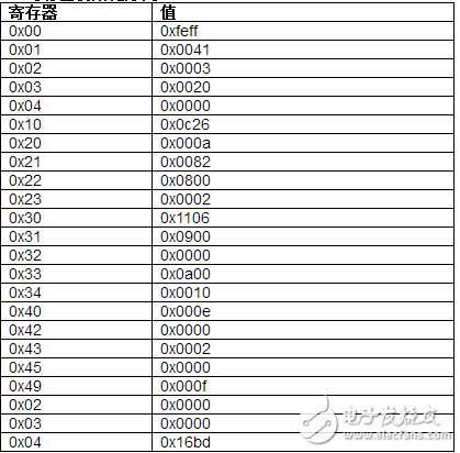
1. Follow the register initialization sequence shown in Table 1 to power up the device. By default, the chip works in automatic frequency band calibration mode. Set Register 0x02, Register 0x03 and Register 0x04 according to the desired LO frequency.
Table 1. Register initialization sequence
2. Read the lock detection (LD) status bit. If LD is 1, it indicates that the VCO is locked.
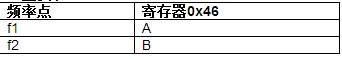
3. Read back the bits [5: 0] of register 0x46 through the serial peripheral interface (SPI). Assuming its value is A, save all the register values ​​corresponding to the LO frequency required in the system to the EEPROM. From this, a table of frequencies and related register values ​​can be determined (see Table 2).
Table 2. Lookup table
4. To shorten the LD time, place the ADRF6820 in manual frequency band selection mode and manually program with the data collected in step 3. The manual programming steps are as follows:
a) Set register 0x44 to 0x0001: disable the band selection algorithm.
b) Set bit 7 of register 0x45 to 1, thereby setting the VCO band source to the saved band information, not from the band calculation algorithm. Use the register value recorded in step 3 to set bits [6: 0] in register 0x45.
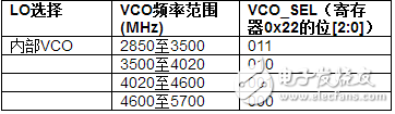
c) Select the appropriate VCO frequency range through Register 0x22, Bits [2: 0] (see Table 3).
Table 3. VCO frequency range
d) Update register 0x02, register 0x03 and register 0x04 according to the required frequency. Register 0x02 sets the divider INT value, which is the integer part of the VCO frequency / PFD; Register 0x03 sets the divider FRAC value, that is (VCO frequency / PFD? INT) × MOD; Register 0x04 sets the divider MOD value, which is PFD / Frequency resolution.
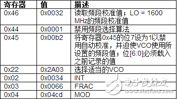
e) Monitor the LD to check whether the frequency is locked. For example, PFD = 30.72 MHz and LO = 1600 MHz.
Table 4. Manual band calibration register sequence
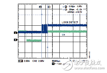
Figures 1 and 2 show the lock detection time in automatic band calibration mode and manual band calibration mode, respectively. In Figure 2, a high level on line 1 (lock detection) indicates that the PLL is locked. Line 2 (LE) represents the LE pin and is a trigger signal. Note: The lock detection time must be read from low to high.
In automatic band calibration mode, the lock time is about 4.5 ms; in manual band calibration mode, the lock time is about 360 μs. The measurement conditions for the data are 20 kHz loop filter bandwidth and 250 μA charge pump current configuration.
Figure 1. Lock time in automatic band calibration mode, tested with a signal source analyzer
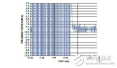
Figure 2. Lock time in manual band calibration mode, tested with an oscilloscope
in conclusion
With manual frequency band selection, the lock time is reduced from a typical value of 4.5 ms to a typical value of 360 μs. For each frequency, first use automatic frequency band selection to determine the best frequency band value and save it. Because the optimal frequency band value varies from device to device, this procedure must be performed for each ADRF6820. The VCO frequency band does not need to be updated due to temperature changes.
Super AC Contactor is exactly copy schneider newest model.The up parts and base will be easy opened to change the coils. On the top of Magnetic AC Contactors, there is a transparent cover for dust improved purpose.
Super AC Contactor is suitable for using in the circuits up to the rated voltage 660V AC 50Hz or 60Hz,rated current 95A.It's mainly used for making and breaking electric circuits at a long distance and for frequent starting/stopping & controlling AC motors. Combined with the auxiliary contact group,air delayer,machine interlocking devence etc,it is combined into the delay contactor,mechanical interlocking device etc,it is combined into the delay contactor,mechanical interlocking contactor,startriangle starter,with the thermal relay,it is combined into the electromagnetic starer.
111")
Super AC Contactor,Electric Magnetic Contactor,Alternating Current Contactor,AC Contactor Alternating Current
Ningbo Bond Industrial Electric Co., Ltd. , https://www.bondelectro.com