Overview of Voltage Measurement <br><br> Voltage is the difference in potential between two points of an electrical or electronic circuit in volts. Used to measure the potential energy of the electric field in the electric current formed in the electric conductor.
Most measuring devices are capable of measuring or reading voltages. Two common voltage measurements are direct current (DC) and alternating current (AC).
Although voltage measurement is the simplest of various analog measurement forms, noise factors present unique challenges to voltage measurement.
How to Make a DC Voltage Measurement <br> Although many sensors can output the DC voltage measured by a data acquisition device, the original intention of this white paper is to investigate the general DC voltage measurement that does not include an intermediate sensor setup.
Voltage Measurement Basics
In order to understand how to measure the voltage, it is essential to understand the background knowledge of the measurement method. Essentially, the voltage is the potential difference between two points of interest in the circuit. However, one often confused place is to determine the measurement reference point. The measurement reference point is the level that is referenced during measurement.
Reference point method
There are essentially two ways to measure voltage: ground reference and differential
Ground reference voltage measurement
One method is to use a common point or "ground" as a reference for measuring voltage. In general, these "grounds" are stable and generally around 0V. The term "ground" originates from historical convention applications that connect the signal directly to ground to ensure that the potential is 0V.
When the channel encounters the following conditions, you can use the ground reference input connection:
High input signal level (greater than 1V)
The length of the connection between the signal and the device is less than 10 inches (3m)
The input signal is shared with other signals. A reference point The ground reference is provided by the measuring device or the external signal under test. When the device provides ground, this setting is called ground referenced single-ended mode (RSE). When provided by the signal, this setting is referred to as non-reference single-ended mode (NRSE).
Most instruments provide a similar pin arrangement for analog input measurements. The following example shows this type of method. The NI CompactDAQ chassis and the NI 9205 analog input module are used in the measurement.
Figure 1 shows the RSE voltage measurement wiring diagram using the NI 9205 and NI cDAQ-9172 and the pin definitions for the module. In Figure 1, pin 1 corresponds to the analog input 0 (AI0) channel and pin 17 corresponds to the common ground (COM).
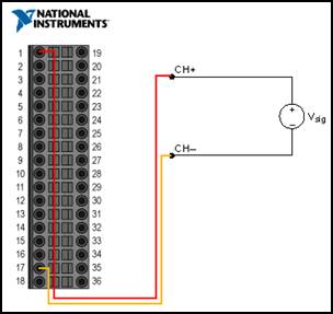
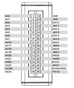
Figure 1. Reference to single-ended mode
Figure 2 shows the NRSE voltage measurement wiring diagram using the NI 9205 and cDAQ-9172. In the figure, pin 1 corresponds to the "analog input 0 (AI0)" channel, and pin 35 corresponds to the "AISENSE" channel. This channel is specifically designed for NRSE measurements and can detect the voltage to ground provided by the signal.
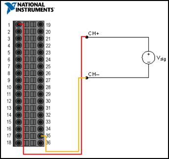
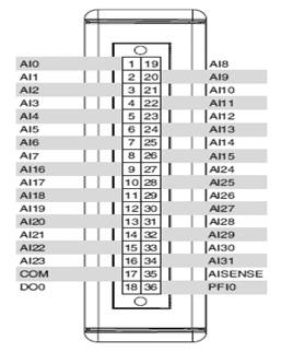
Figure 2. Non-reference single-ended mode
Differential voltage measurement
Another way to measure the voltage is to determine the differential voltage between two separate points in the circuit. For example, measuring the voltage across a single resistor requires measuring across the resistor. The voltage difference is the voltage across the resistor. Differential voltage measurements are often useful in determining the voltage or source of a signal passing through a separate component of a circuit.
Differential input connections can be used when the channel encounters the following conditions:
Low input signal level (less than 1V)
Connection wire between signal and equipment greater than 10 feet (3 meters)
The input signal requires an isolated ground reference point or feedback signal line through a noisy environment. Figure 3 shows a differential voltage measurement wiring diagram using the cDAQ-9172 with the NI 9205 installed. In the figure, pin 1 corresponds to the "analog input 0 (AI0)" channel, and pin 19 corresponds to the "analog input 8 (AI8)" channel.
In differential mode, the negative signal is directly connected to an analog input pin that is paired with the analog channel to which the positive signal is connected. For example, "analog input 0" is connected to the positive terminal, and "analog input 8" is connected to the negative terminal signal; "analog input 1" is connected to the positive terminal, and "analog input 9" is connected to the negative terminal signal; The disadvantage of differential mode is that the number of analog input measurement channels is reduced by half.
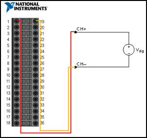
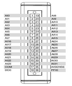
Figure 3. Differential mode
Source type
Before configuring input channels and connecting signals, you should first determine whether the source is floating or grounded.
Floating signal source
The floating source is not connected to the building grounding system but has an isolated ground reference point. Examples of floating sources are transformers, thermocouples, battery-powered devices, optocoupler and isolation amplifiers. An instrument or device that has isolated outputs is a floating signal source. The ground reference point of the floating signal must be connected to the ground of the device to establish a local or onboard reference point for the signal. Otherwise, the measured input signal will fluctuate beyond the common-mode input range.
Ground signal source
The ground signal source is connected to the building grounding system. Therefore, under the assumption that the measuring equipment and the signal source are connected to the same power supply system, the signal source is connected to the common grounding point associated with the equipment. Non-isolated outputs of instruments and equipment that access the building's power supply system fall into this category. The potential difference between the two instrument grounds connected to the same building power supply system is usually between 1 and 100 mV, but if the connection of the distribution line is unreasonable, the difference will be much higher. If the ground source measurement method is wrong, this difference is the measurement error. Following the connection instructions of the ground source can eliminate the potential difference from the ground of the signal under test.
Figure 4 shows the source type and the optimized wiring diagram based on each measurement method. Please note that depending on the signal class, a voltage measurement method is more effective than other methods.
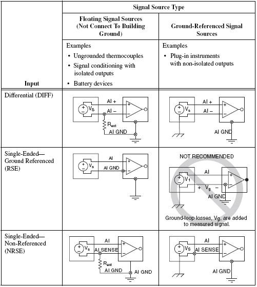
Figure 4. General signal source category and corresponding recommended input configuration
High voltage measurement and isolation
There are many factors to consider when measuring high voltages. When designing a data acquisition system, the first question raised is whether the system is safe or not. Performing high-voltage measurements not only harms the equipment, the unit under test, but also poses a danger to the personal safety of your individual and colleagues. In order to ensure system safety, insulation measurement equipment should be used to provide an insulation barrier between the user and dangerous voltage.
Isolation is a method of physically and electrically separating a measuring device into two parts, which can be divided into electrical isolation and safety isolation. Electrical isolation is not connected between the two electrical systems. Electrical isolation can disconnect the ground loop, increase the common-mode range of the data acquisition system, and can also flatten the voltage at the reference point of the signal to the ground of a single system. Safety Isolation Reference Standards have special provisions for protecting individuals from dangerous voltages, and evaluate the performance of electrical systems to avoid the occurrence of high voltage and transient voltage breakdown boundary transmission to other electrical systems that the user may be exposed to.
Installing isolation devices in a data acquisition system has three main functions: preventing ground loops, suppressing common-mode voltages, and providing security.
Ground loop
Ground loops are the most common source of noise in data acquisition applications. This happens when the two connected ends of the circuit are at different ground potentials, causing current to flow between the two points. The local ground potential of the system may be higher or lower than the ground voltage of the nearest building, and nearby lightning strikes may also cause this difference to rise to several hundred or several thousand volts. This extra voltage not only causes a significant error in the measurement itself, but also the current in the current generates a coupling voltage in the nearby wire. This error can occur with transient signals and periodic signals. For example, if a ground loop is routed through a 60-Hz AC power line, unnecessary AC signals will appear as periodic voltage errors in the measurement.
When a ground loop exists, the measured voltage Vm is the sum of the signal voltage Vs and the potential difference Vg, which is the potential difference between the signal source ground and the measurement system ground (as shown in Figure 5). This potential is usually not a DC level; therefore, a noise-inducing measurement system is formed that contains the power line frequency (60 Hz) component during the reading process.
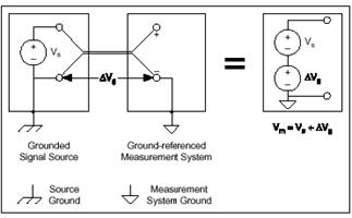
Figure 5. The ground signal measured by the ground reference system introduces a ground loop
To avoid ground loops, make sure that there is only one ground reference point in the measurement system, or use isolated measurement hardware. The use of isolated measurement hardware eliminates the connection path between the signal source ground and the measurement device, which prevents current flow between multiple ground points.
In the previous article we mentioned the NI CompactDAQ configuration. The NI 9229 analog input module provides 250V channel-to-channel isolation.
Common mode voltage
An ideal differential measurement system only reflects the potential difference between the two terminals, the positive (+) and negative (-) inputs. The differential voltage between the two conductors is a valid signal, but unnecessary signals are likely to exist, which is common on both conductors of differential two-wires. This voltage is commonly known as common-mode voltage. The ideal differential measurement system can completely suppress common-mode voltages, not to mention measurements. However, practical equipment has many limitations that limit the ability to reject common-mode voltages. These limitations are described by parameters such as common-mode voltage range and common-mode rejection ratio (CMRR).
The definition of common-mode voltage range refers to the maximum allowable voltage swing of each input of the measurement system to the ground. Violation of this restriction will not only result in measurement errors but may also damage the components on the board.
The common-mode rejection ratio describes the ability of the measurement system to reject common-mode voltages. The higher the common-mode rejection ratio, the more significant the suppression of the common-mode voltage is.
In non-isolated differential measurement systems, there are still conductive paths between the input and output of the circuit. Therefore, the electrical characteristics of the amplifier limit the rejection of common-mode signal levels at the input. Using an isolation amplifier eliminates the conductive electrical path, and the common-mode rejection ratio also increases significantly.
Isolation topology
When configuring a measurement system, it is important to understand the device's isolation topology. Different topologies have different related cost and speed considerations.
Channel to channel
The most robust isolation topology is channel-to-channel isolation. In this topology, there is isolation between each channel and other non-isolated system components. In addition, each channel has its own isolated power supply.
Considering speed, there are a variety of structures to choose from. Using an analog-to-digital converter (ADC) and an isolation amplifier for each channel, the speed can be significantly faster because all channels can be connected in parallel. The NI 9229 and NI 9239 analog input modules provide channel-to-channel isolation for maximum measurement accuracy.
A cost effective and relatively slow architecture is the multiplexed input channels multiplexed onto an ADC.
Another way to provide channel-to-channel isolation is to share an isolated power supply for all channels. In this case, unless you are using a front-end attenuator, the amplifier's common-mode range is limited by the power supply path.
Another isolation topology includes combining or aggregating multiple channels to share a single isolation amplifier. In this topology, the common-mode voltage difference between the channels is limited, but the common-mode voltage between the channel groups and the non-isolated parts of the measurement system may be large. Channels are not isolated, but channel groups are isolated from other groups and grounds. This topology is a low-cost isolation solution because this design shares an isolation amplifier and power supply.
Most NI C Series analog input modules are group-isolated, such as the NI 9201 and NI 9221, which provide lower-cost, accurate analog measurements.
Start Browsing Your Measurements: NI LabVIEW
Once the sensor is connected to the measurement instrument, you can use the LabVIEW graphical programming software to visualize and analyze the data. (See Figure 6)
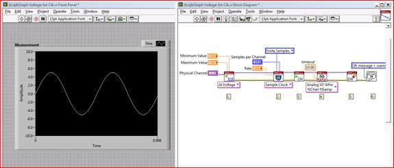
Figure 6. LabVIEW Voltage Measurement
Excerpt from: NI "General Measurement Guide"
Alumina Ceramic Discs,Alumina Ceramic Plate,Coffee Machine Ceramic Discs,Al2O3 Ceramic Core
Yixing Guangming Special Ceramics Co.,Ltd , https://www.yxgmtc.com