Recently, media reports such as China Science and Technology Network, Science and Technology Daily, and China News Network, Professor Lu Rongsheng of the College of Instrument Science and Optoelectronic Engineering of Hefei University of Technology proposed a new method of back-error compensation to achieve the accuracy of three-dimensional topography measurement of objects. The efficiency has been greatly improved. The results were published in the fourth issue of the Journal of Optics, a prestigious academic journal published a few days ago, and were included in the cover story and excellent paper of the current period.
Fringe Projection Phase Shift Three-dimensional topography measurement technology uses a digital projector to project fringes onto the surface of the measured object. After the image sensor acquires the fringe image modulated by the object, it obtains the main value (package) phase map and unwrapping of each pixel. The phase diagram calculates the three-dimensional topographic information of the measured object. At present, the active, passive, and reverse three phase error compensation methods commonly used have their own deficiencies in terms of accuracy, system parameters, calibration methods, and the use environment. In the measurement process, phase resolving difficulties, measurement accuracy, details of the object's topography are concealed, or information is lost.
Researchers have discovered that when projecting an object to be measured onto a compensated phase shift fringe with the same highest frequency and a certain amount of phase shift, the phase errors in the two main value phase maps obtained are equal in magnitude and opposite in direction. Taking advantage of this feature, the team innovatively proposed an inversion error compensation method that compensates for phase errors in the main-value phase map and combines multi-frequency phase shifts to obtain absolute phase. This method only needs to project one more compensation fringe pattern with the same frequency as the highest frequency. The nonlinear error of the system is eliminated by reverse mutual cancellation, and the high-precision absolute phase value is obtained. The phase error of the system need not be calibrated in advance, and the measurement accuracy is greatly improved. At the same time, the measurement time is significantly shortened.


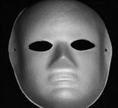
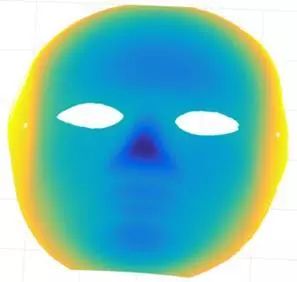
Photograph of the measured object (Figure 1) Phase diagram of the main value (Figure 2)
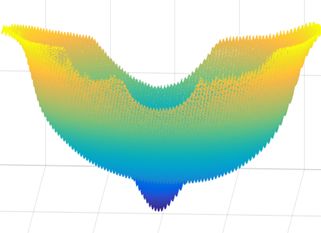
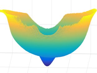
Positive absolute phase recovery after error compensation (Figure 3)
Using the characteristics that the phase error values ​​in the two main-value phase maps are equal in magnitude and opposite in sign, the high-precision absolute phase values ​​are obtained by superposition and mutual offset.


Partial top-down error compensation front phase map (less smoothness)
The effect of the above error compensation (surface smooth)
The experimental results show that this method solves the phase jump problem caused by voids, staircases, shadows, or spatial discontinuities on the surface of the measured object, and avoids the high-frequency fringe poles mixed and falling caused by complex contours. When the measurement environment changes, it is no longer necessary to recalibrate the measurement system, and it is not easy to be disturbed by environmental factors during the measurement process, thereby greatly improving the measurement efficiency.
According to reports, this achievement will have broad application prospects in fields such as smart manufacturing, reverse engineering, and biomedicine. At present, this result has been applied to the rapid detection of the unevenness of the surface of the large-area liquid crystal and filter substrate glass of the sixth-generation line and the 8.5-generation line.
We desing and manufacturer various LCD Driver/controller for many brand LCDs to support VGA Input,HDMI Input,DVI Input,Video input.
OEM and ODM service is also available,we make the LCD driving board accroding to your request.Small MOQ and fast leadtime.
Displays real-time data for your controller. In addition to current-voltage, current and temperature also limit information about the state of applications and controllers.
Thin-film transistor liquid crystal display (TFT-LCD) has the characteristics of light weight, flat plate, low power consumption, no radiation, excellent display quality, etc. Its application field is gradually expanding, has developed from audio-visual products, notebook computers and other displays to desktop computers, engineering workstation (EWS) monitors. LCD requirements are also developing towards high resolution and high color. Due to the CRT monitor and LCD screen has different display characteristics, both display signal parameters are also different, so the computer (or MCU) and LCD screen LCD driver circuit is required between design, its main function is through the electrode potential signal output to the LCD, peak modulation, frequency and other parameters to establish the ac drive electric field.
Lcd Driver,Lcd Driver Board,Lcd Controller Board,Universal Lcd Controller Board
TONYA DISPLAY LIMITED , https://www.tydisplay.com