The DC/DC conversion converts a fixed DC voltage into a variable DC voltage, also known as DC chopping. It generally has several functional modules such as PWM (Pulse Width Modulation) module, E/A (error amplifier module), and comparator module. The working principle is as follows: the output is connected to the FB pin through the FB (feedback circuit), and the feedback voltage VFB is compared with the set comparison voltage Vcomp to generate an error voltage signal, and the error voltage signal is input to the PWM module, and the PWM is based on the magnitude of the error voltage. Adjusting the duty cycle to achieve the purpose of controlling the output voltage, the oscillator acts to generate a triangular wave of the PWM operating frequency. After the triangular wave is chopped by the chopping voltage, a square wave is generated, and the square wave controls the conduction time of the MOSFET to control Output voltage.
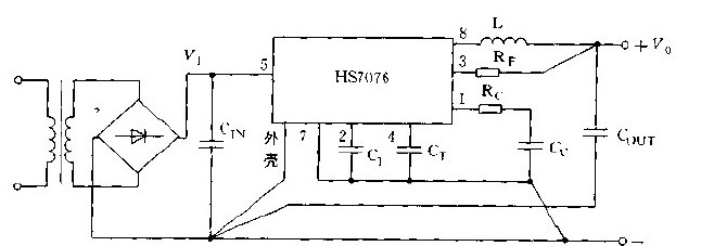
In the above figure, the output voltage Vo=2.5×(1+Rf/4), C is the filter capacitor, Ct is the timing capacitor, and Cc and Rc are the compensation circuits. The circuit operates under conditions of V1=10~35V and I1=1~6A.
Windows Pocket Pc,Handheld Mobile Computer,Handheld Pcs,Microsoft Pocket Pc
SUNLUX IOT Technology (Guangdong) INC. , https://www.sunluxbarcodereader.com