Application case of Modbus to profinet gateway in Tianjin Fuel Company
This article mainly introduces the use of the modbus-to-profinet gateway PNMD485-K20 connected to electric valves manufactured by Beijing Kaijiang Intelligent Automation Technology Co., Ltd. (hereinafter referred to as Kaijiang Intelligent):
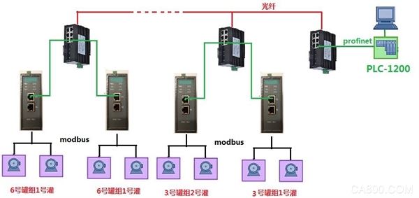
1. Case Description: This case is on the site of the Tianjin Fuel Oil Company. The company has 150,000 tons of oil storage facilities. This case is applied to the 3-6 tank group. There are 6 to 12 different tanks in each tank group. Each tank has two electric valves to control the tank's inlet and outlet. The electric valve adopts the communication protocol of modbus. The PLC uses the Siemens 1200 series PLC. The field adopts PROFINET industrial Ethernet communication and converts it through modbus to profinet gateway. Because the distance between the oil tank and the control room is far away, WYS208/2F two-fiber six-electrical fiber Ethernet switches manufactured by Kaijiang Intelligent are adopted at the site. The purpose of this case is to control the oil inlet and outlet switches of the oil tank and the position of the electric valve in the central control room.
2. Case description: The modbus-to-profinet gateway PNMD485-K20 produced by Kaijiang Intelligent does not need to be programmed when it is in use. Simply configure it according to the communication point table that is connected to the device. The following points need to be concerned:
(1) Is the connected device the master or slave of MODBUS communication?
The electric valve in this example is used as a MODBUS slave, so the PNMD485-K20 serves as the MODBUS master.
(2) How many devices are connected? What is the address of each device? What is the format of the MODBUS communication protocol for each device?
In this example, each tank uses a PNMD485-K20. Each PNMD485-K20 has two electric valves. The address of the electric valve equipment is set to No. 1 and No. 2, respectively. (In this case, there are 6 to 12 oils in each tank area. Cans are set in the same way)
Baud rate: 19200 Data bits: 8 Check digits: None Stop bits: 1
(3) Which parameters are connected to the device need to be read and written in the PLC. Which of these parameters are in the MODBUS address area and what is the MODBUS address of the parameter?
The communication protocol is shown in the following table: In this case, the position of the electric valve (modbus address 40002) needs to be read, and the stop, close, and open commands of the valve are written (bit0, bit1, bit2, ...) of the modbus address 40000
Table I: 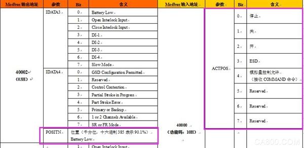
(4) The IP address and name of the PLC
This case Siemens PLC's IP address 192.168.20.208, PLC name: PLC_1
(5) Application network diagram:
3. Case configuration: Import XML to create a new project
(1) Open the Portal Software "TIA Portal V13" Create a new project -> enter the project name -> create. Figure 3-1:

Figure 3-1
(2) Click the project view, as shown in Figure 3-2
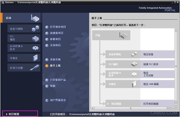
Figure 3-2
(3) Installing XML files 3-3, 3-4
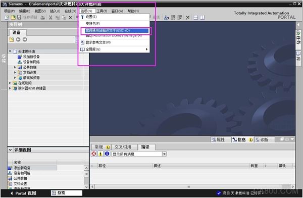
Picture 3-3
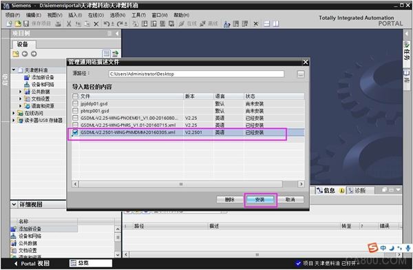
Figure 3-4
(5) Hardware Configuration ---- Create a PLC, as shown in Figure 3-5
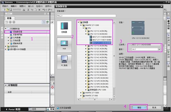
Figure 3-5
(6) Hardware configuration ---- Create a PN slave station, as shown in Figure 3-6

Figure 3-6
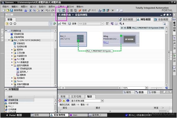
(7) Hardware Configuration ---- Build a PROFINET link, as shown in Figure 3-7, 3-8
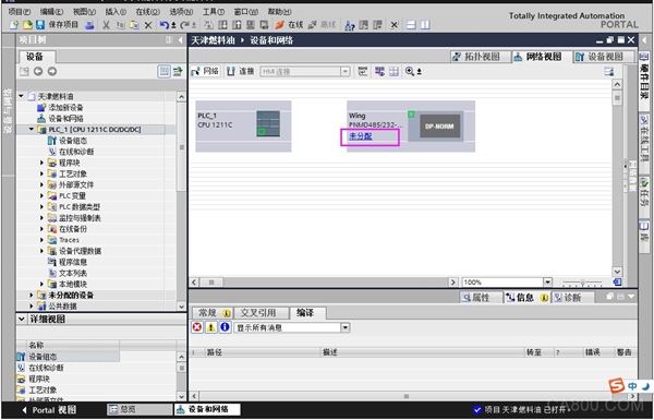
Figure 3-7
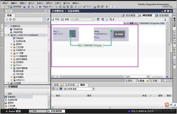
Figure 3-8
(8) Hardware configuration ---- Modify the IP address and name of the Modbus-to-ProfiNet gateway PNMD485-k20 (IP address must be on the same network segment as the actual PLC address, and the name must be the same as PNMD485-k20). 3-9
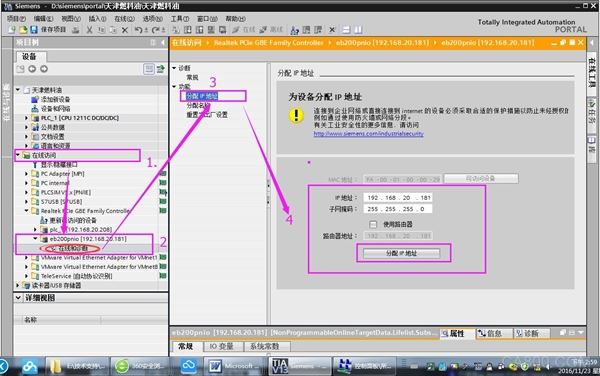
Figure 3-9
(9) Hardware Configuration ---- Set the IP address and name of the PLC (the parameters set here must be consistent with the actual PLC parameters), as shown in Figure 3-10
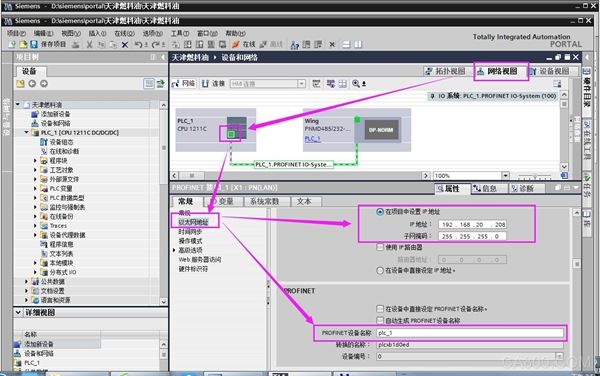
Fig. 3-10
(10) Hardware configuration ---- Set the IP address and name of the configured Modbus to ProfiNet gateway PNMD485-K20 (the parameters set here must be consistent with the actual PLC parameters), as shown in Figure 3-11
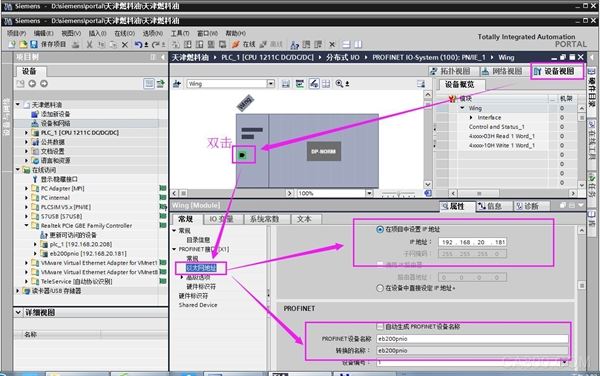
Fig. 3-11
(11) Hardware configuration ---- configuration configuration of the module parameters (including the connected device's baud rate, parity bits and other information, the parameters set here and the actual parameters of the equipment being connected), as shown in Figure 3 -12
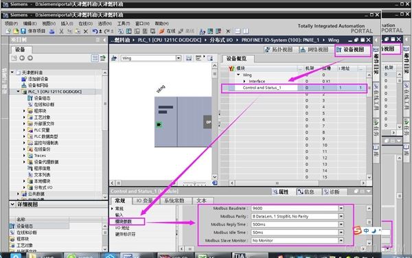
Fig. 3-12
(12) Hardware configuration ---- configure the master station to read and write connected device messages, as shown in Figure 3-13, 3-14, 3-15
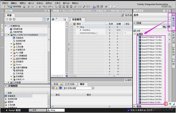
Figure 3-13
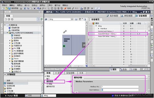
Figure 3-14
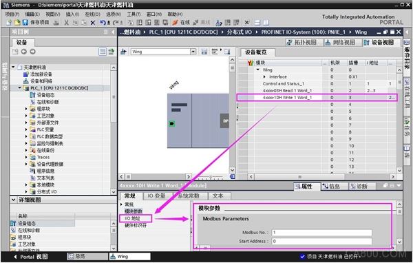
Fig. 3-15
(13) Hardware Configuration ---- Start Modbus to ProfiNet Gateway, as shown in Figure 3-16
Picture 3-16
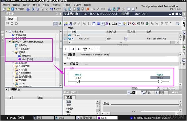
(14) Hardware Configuration ---- Compile and Download Program, as shown in Figure 3-17
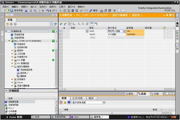
(15) Read-write parameter test: IW2 reads the parameters of the electric valve MODBUS address 40002. As shown in Figure 3-18
Bit 2 of QW2 indicates the valve is opened. When this value is set, the valve opening action can be seen. Similarly, stop and close actions can be performed.
Summary: After the above simple configuration of Modbus to ProfiNet gateway, users can easily complete the protocol conversion of PROFINET and MODBUS and read and write MODBUS device data under the PROFINET bus protocol.
Huawei Touch Screen Price,Mobile Phone Touch Panel,Mobile Phone LCD,Mobile Touch Screen Manufacturers
Dongguan Jili Electronic Technology Co., Ltd. , https://www.touchmanufactor.com