
The working principle of capacitor buck is not complicated.
It works by limiting the maximum operating current by the capacitive reactance produced by the capacitor at a certain AC signal frequency.
For example, at a power frequency of 50 Hz, a 1 uF capacitor produces a capacitive reactance of approximately 3180 ohms. When an AC voltage of 220V is applied across the capacitor, the maximum current flowing through the capacitor is approximately 70 mA. Although the current flowing through the capacitor is 70 mA, there is no power consumption on the capacitor. If the capacitor is an ideal capacitor, the current flowing through the capacitor is the imaginary current, and the work done is reactive power.
According to this feature, if we connect a resistive component in series with a 1uF capacitor, the voltage obtained across the resistive component and the power dissipation it generates depends entirely on the characteristics of the resistive component.
For example, we connect a 110V/8W bulb in series with a 1uF capacitor. When connected to an AC voltage of 220V/50Hz, the bulb is illuminated and emits normal brightness without being burned. Because the 110V/8W bulb requires 8W/110V=72mA, it matches the current limiting characteristics of the 1uF capacitor. Similarly, we can also connect a 5W/65V bulb and a 1uF capacitor in series to 220V/50Hz AC. The bulb will also be lit without being burned. Because the 5W/65V bulb also has an operating current of about 70mA. Therefore, the capacitor buck is actually using the capacitive reactance current limit. The capacitor actually acts as a limiting current and dynamically distributing the voltage across the capacitor and the load.
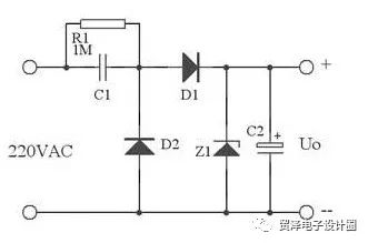
The following figure shows the typical application of RC capacitor. C1 is the step-down capacitor. R1 is the bleeder resistance of C1 when the power is off. D1 is the half-wave rectifier diode. D2 provides the discharge circuit for C1 in the negative half of the mains. Otherwise When capacitor C1 is fully charged, it will not work. Z1 is a Zener diode and C2 is a filter capacitor. The output is a stable voltage value of Zener diode Z1.
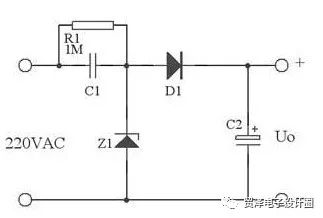
In practical applications, the following figure can be used instead of the above figure. Here, the Z1 forward characteristic and the reverse characteristic are used, and the reverse characteristic (that is, its voltage regulation characteristic) is used to stabilize the voltage, and the forward characteristic is used in the commercial power. A negative half cycle provides a discharge loop for C1.
In larger current applications, full wave rectification can be used. As shown below:
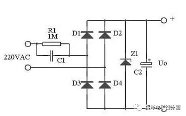
At small voltage full-wave rectified outputs, the maximum output current is:
Capacitance: Xc=1/(2Ï€fC)
Current: Ic = U/Xc=2Ï€fCU
Pay attention to the following points when using capacitor step-down:
1. Select the appropriate capacitor according to the current of the load and the operating frequency of the AC, not the voltage and power of the load.
2, the current limiting capacitor must use non-polar capacitors, absolutely can not use electrolytic capacitors. Moreover, the withstand voltage of the capacitor must be above 400V. The most ideal capacitor is an iron-shell oil-immersed capacitor.
3. Capacitor buck cannot be used for high power conditions because it is not safe.
4. Capacitor step-down is not suitable for dynamic load conditions.
5. Similarly, the capacitor step-down is not suitable for capacitive and inductive loads.
6. When DC operation is required, half-wave rectification should be used as much as possible. Bridge rectification is not recommended. And to meet the conditions of a constant load.
1.0mm (.039″) Pitch Pin Headers
Overview
Antenk offers a variety of high quality and competitively priced 1.0mm pitch single, dual, three, quad row pin (male) headers used in many board-to-board PCB connections, fitting small-sized, densely-packed devices.
This low-profile component is made from high-temperature thermoplastic and is offered with several means of connections and mounting styles such as through-hole (THM) or surface mount (SMT) and can be in vertical (straight), elevated or at a right angle configuration/orientation dissipating current of about 1.0 A or less.
The pin (male) header is generally mated with receptacle or stackable header connectors (female sockets). This types of pin headers are suitable for PCB board to board connection or for signal transmission application.
Applications of 1.0mm Pitch Pin Headers
Its small size is most suitable for PCB connections of small equipment and devices such as WiFi equipment, gaming consoles, measurement instruments, and other equipment in need of a special interface to become interconnected
Mount Type: Through-hole vs Surface Mount
At one side of this pin header is a series of pins which can either be mounted and soldered directly onto the surface of the PCB (SMT) or placed into drilled holes on the PCB (THM).
Through-Hole (Poke-In)
Best used for high-reliability products that require stronger connections between layers.
Aerospace and military products are most likely to require this type of mounting as these products experience extreme accelerations, collisions, or high temperatures.
Useful in test and prototyping applications that sometimes require manual adjustments and replacements.
1.0mm vertical single row header, 1.0mm vertical dual row header, 1.0mm Elevated single row pin header, 1.0mm Elevated dual row pin Header, 1.0mm Right-angle single row header and 1.0mm Right-angle dual row header are some examples of Antenk products with through-hole mount type.
Surface-Mount
The most common electronic hardware requirements are SMT.
Essential in PCB design and manufacturing, having improved the quality and performance of PCBs overall.
Cost of processing and handling is reduced.
SMT components can be mounted on both side of the board.
Ability to fit a high number of small components on a PCB has allowed for much denser, higher performing, and smaller PCBs.
1.0mm Right-angle Dual Row pin header, 1.0mm SMT Single row pin header, 1.0mm SMT Dual row pin header and 1.0mm Elevated Dual Row Pin Header are Antenk`s SMT pin headers.
Soldering Temperature for 1.0mm Pitch Pin Headers
Soldering SMT pin header can be done at a maximum peak temperature of 260°C for maximum 60 seconds.
Pin-Type: Vertical (Straight) and Right-Angle
1.0mm pitch headers may be further classified into pin orientation as well, such as vertical or straight male header or right-angle male header.
Vertical or Straight Pin (Male) Header Orientation
One side of the series of pins is connected to PCB board in which the pins can be at a right-angle to the PCB surface (usually called "straight" or [vertical") or.
Right-Angle Pin (Male) Header Orientation
Parallel to the board's surface (referred to as "right-angle" pins).
Each of these pin-types have different applications that fit with their specific configuration.
PCB Connector Stacking
Elevated Pin Header Orientation
Elevated pins aka Stacked Pins or Mezzanine are simply stacked pin headers providing an exact distance requirement between PCBs that optimizes electrical reliability and performance between PCB boards.
Profile Above PCB
This type of configuration is the most common way of connecting board-to-board by a connector. First, the stacking height is calculated from one board to another and measured from the printed circuit board face to its highest insulator point above the PCB.
Single, Dual or Multiple Number of Rows
For a 1.0mm straight or vertical male pin header, the standard number of rows that Antenk offers ranges from 1 to 2 rows. However, customization can be available if 3 ,4 or n number of rows is needed by the customer. Also, the number of contacts for the single row is about 2-50 pins while for dual row, the number contacts may vary from 4-100 pins.
Pin Material
The pins of the connector have been designed with copper alloy. With customer`s demand the pins can be made gold plated.
Breakaway design
The pin headers are also equipped with a breakaway design making them fully compatible with their female receptacles.
Custom 1.0mm Pitch Pin Headers
Customizable 1.0 mm pitch pin headers are also available, making your manufacturing process way faster as the pins are already inserted in the headers, insulator height is made at the right size and the accurate pin length you require is followed.
Parts are made using semi-automated manufacturing processes that ensure both precision and delicacy in handling the headers before packaging on tape and reel.
The tape and reel carrier strip ensures that the headers are packaged within accurately sized cavities for its height, width and depth, securing the headers from the environment and maintaining consistent position during transportation.
Antenk also offer a range of custom Tape and reel carrier strip packaging cavities.
Male Header Pins,1.0Mm Male Header,1.0Mm Pin Header,1.0Mm Male Header Pins, 1.0mm THM Male Header, 1.0mm SMT Male Header
ShenZhen Antenk Electronics Co,Ltd , https://www.antenkconn.com