With the continuous development of science and technology and electronics technology, how to easily and effectively realize the problem of uniform display, large-area illumination, high-brightness and high-resolution illumination, and prolong the life of organic light-emitting diodes, etc. It is the technical challenge we face in the future. Today, Xiaobian brings you several examples of active and passive oled display driver designs on weekdays for everyone to use as an electronic design reference.
First, the drive control SSD1303 realizes 96x64 dot matrix PM-OLEDThis example uses Solomon's OLED display driver circuit SSD1303, combined with AT89C51 microcontroller to achieve the method of driving OLED display. The SSD1303 is a dedicated OLED display control driver circuit that integrates a controller, row driver and column driver.
In the experiment, the anode material of OLED structure adopts ITO (indium tin oxide), and the cathode uses Mg and other stable metal alloys as Mg:Ag to improve the quantum efficiency and stability of the device, and can form a stable on the organic film. Sturdy metal film.
The PM-OLED uses a common matrix cross screen. The OLED is located between the cross-arranged anode and cathode. By strobing the anode and cathode combinations, the illumination of each OLED can be controlled.
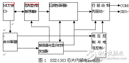
The internal circuit block diagram of the SSD1303 chip is shown in Figure 1:

The SSD1303 chip is mainly composed of an MCU interface, a command decoder, an oscillator, a display timing generator, a voltage control and current control, a region color decoder, and a graphic display data memory (GDDRAM), a row driver, and a column driver. This IC's dedicated OLED driver solution optimizes OLED display performance and reduces power consumption. The device is available in a TCP/TAB package. It has a graphic display with a maximum of 132 & TImes; 64 dot matrix, a logic power supply of 2.4 to 3.5V, a power supply of 7.0 to 16V for the OLED panel, a maximum current of 320μA for the column output, and a maximum current of 45mA for the line input. Sleep mode less than 5μA, 256 levels of contrast control, programmable frame rate, with several MCU interfaces, such as 68/80 parallel bus and serial peripheral interface, 132 & TImes; 65bit display buffer, can be scrolled vertically, support partial display, work Temperature: -40 oC to 85 oC.
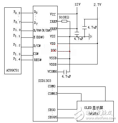
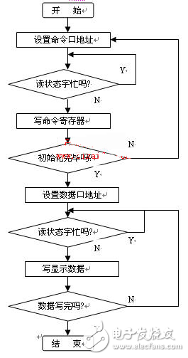
The whole system consists of three parts: single chip microcomputer, control drive circuit SSD1303 and OLED display. The pins of SSD1303 and MCU interface are: DO~D7 is the data bus interface with the single chip microcomputer, R/W(RW#) is the read/write selection signal. D/C is the data/command selection signal, CS# is the chip select signal, active low, E(RD#) is the enable signal, and RES# is the reset signal. The single-chip microcomputer adopts the low-power and high-performance AT89C51 produced by ATMEL Company. The hardware wiring of AT89C51 and SSD1303 and the display is shown in Figure 2. P1.0, P1.1, P1.2, P1.3 and P1.4 respectively Connected to R/W (RW#), D/C, CS#, E(RD#), and RES# of SSD1303, P0 port is connected to the data bus of SSD1303. Other pins are connected to VCC to 12V, VDD to 2.7V, VSS to ground, and so on. These pins are controlled by the program below so that the OLED displays the desired Chinese characters or graphics. The main program software flow chart is shown in Figure 3.

Figure 2 The hardware wiring of the single chip AT89C51 and SSD1303 and the display

Figure 3 main program software flow chart
Jiangsu Qilong Electronic Technology Co., Ltd. , https://www.jsqldzkj.com