The core value of the smart grid is to improve energy efficiency, use various high-tech means to improve the operation and management level of all links of transmission, transmission, distribution and power consumption, save resources and protect the environment; smart grid is more suitable for power generation and distribution of multiple energy units. The need of electricity consumption is more suitable for the needs of market-oriented power trading, and is more suitable for customers' self-selection needs.
This article refers to the address: http://
Vehicle to Grid (V2G) technology is the two-way interaction and exchange between electric vehicles and the grid under controlled conditions. It is an important part of “smart grid technologyâ€, applying V2G and smart grid technology. The charging and discharging of the electric vehicle battery is uniformly deployed. According to the established charging and discharging strategy, the remaining electric energy can be controlled and fed back to the power grid in two directions under the premise of satisfying the driving demand of the electric vehicle user.
1 V2G system information flow
V2G embodies energy bidirectional, real-time, controllable, flowing between the vehicle and the grid. The charge and discharge control device has interaction with the grid and interaction with the vehicle. The interactive content includes energy conversion information, customer demand information, Grid status, vehicle information, metering and billing information, etc. Therefore, V2G is a high-end integrated application of many technologies such as power electronics, communication, scheduling and metering, and demand side management.
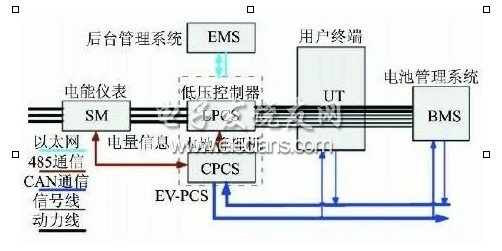
Figure 1 shows the V2G system information map.
SM: smart meter, two-way metering, local information storage, communicate with EV2PCS via RS485, and transmit power information to the UT through EV2PCS;
EV2PCS: Two-way intelligent charging and discharging device, which consists of a low-voltage controller and a local management machine, is used to realize two-way energy interaction between the vehicle and the power grid, and is a key device of the V2G system;
UT: Human-computer interaction terminal is an interface between the electric vehicle user and the power grid, and the user obtains the power consumption and electricity fee information from the user;
BMS: Battery management system, used for collecting and transmitting vehicle battery data, monitoring battery operating status, communicating with EV2PCS via CAN bus, transmitting vehicle information to the background through EV2PCS;
EMS: The background management system communicates with the power grid dispatching system, obtains the grid load information and executes the grid dispatching command, communicates with the EV2PCS, acquires the vehicle state information, and assigns and dispatches the power grid dispatching command.
2 V2G system components
2. 1 bidirectional intelligent charging and discharging device
As a key power component in V2G technology, the two-way intelligent control device is used to realize the bidirectional flow of energy between the power grid and the electric vehicle. It can work in the charging mode and the V2G mode: if the charging working mode is selected, only the charging operation of the vehicle is performed, The vehicle battery energy is fed back to the power grid; if the V2G working mode is selected, the device can charge and discharge the connected vehicle according to the upper and lower thresholds of the vehicle SOC selected by the user on the human-machine interaction terminal, or the default upper and lower thresholds of the SOC of the device. The real-time capacity, controlled time and other information are provided to the background management system, and the background management system issues a charge and discharge control command, and the device performs charging and discharging operations according to the current SOC of the vehicle battery to realize two-way flow of energy.
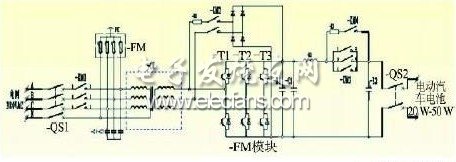
Figure 2 shows the main loop topology of the two-way intelligent control device.
Its topology features are as follows:
(1) Three-phase full-bridge bidirectional PWM conversion can be used to charge and discharge the battery;
(2) Grid communication and electric vehicle battery side are electrically isolated by isolation transformer
(3) At the same time, the isolation transformer can perform voltage matching between AC and DC;
(4) An overload overcurrent Circuit Breaker is configured on the AC side and the DC side;
(5) The AC DC side is equipped with a pre-charging circuit, and the starting mode is flexible;
(6) Adopting a first-stage converter, the topology is simple and the reliability is high.
2. 2 human-computer interaction terminal
The structure of the human-computer interaction terminal system is shown in Figure 3. It is mainly composed of an embedded controller, a touch display screen, a radio frequency card reader, a CAN communication card, a remote monitoring communication expansion card, and a micro printer. The main functions are: interface display, identification, EV2PCS control mode, ticket printing, data management and query, personalized parameter setting, language switching, user operation help and abnormal information prompts.
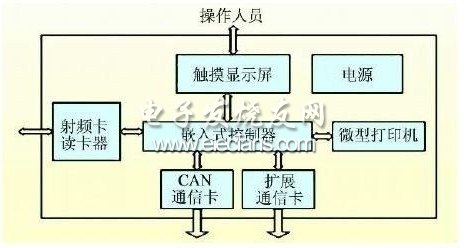
Figure 3 shows the structure of the human-computer interaction terminal system. Figure 3. Back-end management system
The background management system includes a charge and discharge strategy control subsystem and an energy management subsystem; the main function of the charge and discharge strategy control subsystem is to use the appropriate charge according to the total chargeable and discharge capacity, electricity price and real-time load information of the current power grid provided by the energy management system. The discharge strategy algorithm calculates the actual allowable charging or discharging capacity of the power grid, thereby dynamically realizing the two-way energy exchange between the vehicle battery pack and the power grid. The main function of the energy management subsystem is to monitor the working status of the vehicle battery pack in real time and provide the basis for charging and discharging strategies. Data, providing a secondary allocation command for charging or discharging capacity for each EV2PCS.
2. 4 vehicle battery management system
The Battery Management System (BMS) is the most comprehensive device for understanding the battery performance and status of the vehicle. It establishes a connection between the BMS and the EV2PCS, enabling the charging device to understand the battery information in real time, changing its execution strategy and input and output current to ensure vehicle operation. , battery safety and extended service life. The main functions of BMS include: real-time monitoring of battery operating status; data acquisition, display and transmission of voltage, current, temperature, SOC, battery fault diagnosis, alarm and safety protection; fault self-test and diagnosis; charge and discharge equalization; and vehicle control Two-way communication between the system and the intelligent charge and discharge charging device.
2. 5 smart meter
As an important technical component of V2G application, smart meter works as shown in Figure 4. The main functions include two-way metering, two-way communication, event recording (recording meter phase failure, voltage loss, over voltage, current loss, current imbalance, super Power, over-demand, over-voltage, open cover, reverse phase sequence and other events, record clock timing, record data clear, parameter settings, meter power-up and other events).
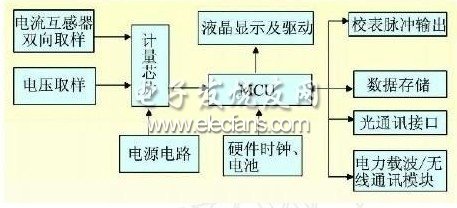
Figure 4 shows the working principle of the smart meter
3 V2G charging and discharging process
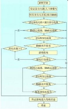
The V2G charging and discharging process is shown in Figure 5 and Figure 6, respectively.
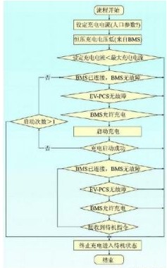
The user first inserts the IC card, and the UT terminal reads the user information through the RF card reader, and displays the remaining power on the card and the last consumption record on the man-machine interface. After the user sets the working mode and related information, the user is prompted. Connect the charging plug correctly and confirm the charging mode or V2G mode.
After the working mode is determined, the UT will confirm whether the charging and discharging interface is correctly connected with the EV2PCS. After confirming, the control signal is sent to the EV2PCS, and the operation of the charging device EV2PCS is started to wait for the background control command.
The EV2PCS executes the background charge and discharge command according to the operation mode selected by the user. During the operation, the UT periodically acquires the meter data, the battery pack data, performs billing, and saves the data. When the parameter set by the user is reached or the user terminates itself, the stop command is sent to the EV2PCS to control the EV2PCS to be powered off, and the user is prompted to charge and discharge on the man-machine interface. After the user unplugs the plug, the print ticket operation can be performed.
4 V2G application scenarios and charging and discharging control strategies
4. 1 V2G application scenario
The future power development model is a transition to distributed power generation and interactive power supply for distributed smart grids, with more emphasis on environmental protection and renewable energy generation applications, which requires the construction of more efficient and distributed energy storage facilities. Energy storage technology is one of the key technologies to realize smart grid. In January 2009, the US Department of Energy Power Advisory Committee consulted the report, using energy storage as a strategic tool for smart grid capacity management, which shows the significance of energy storage technology. As an existing distributed mobile energy storage unit, electric vehicles are used for long-term and successful management of vehicle charging and discharging through smart grid technology. V2G technology will be widely used in smart grids. Research shows that "in parallel with smart vehicles and smart grids, plug-in hybrid electric vehicles (PHEVs) and electric vehicles (EVs) will become an integral part of the distribution system itself within 20 years, providing energy storage, emergency power supply And the stability of the grid." The possible application modes and application scenarios of the proposed V2G are:
(1) Residential area (V2H, Vehicle to Home);
(2) Office buildings (V2B, Vehicle to Bulding);
(3) Large private parking lot;
(4) Supermarkets, hypermarkets or shopping centres;
(5) Government, school office buildings;
(6) Charging the vehicle with clean energy.
4. 2 V2G charge and discharge control strategy
As a mobile energy storage device, the electric vehicle is connected to the power grid, and the two-way interaction with the grid energy is premised on ensuring that the convenience of the user is not affected. At present, the maximum driving range of pure electric small passenger cars is generally less than 200 km, and the actual service life of the battery is less than 1000 cycles, which is far lower than that of conventional fuel vehicles. Therefore, it is very important to adopt appropriate control strategies.
The strategic considerations involve the grid side, the vehicle side, and the user side. The grid side needs to consider the grid real-time load, electricity price, and dispatch center command; the vehicle side needs to consider the battery energy state, input and output power, available time, etc.; the user side mainly considers the user's Driving habits, mileage and special needs. Based on the data of charge and discharge capacity, grid load, electricity price, etc., the appropriate charge and discharge strategy control algorithm is used to obtain the energy information required by the power grid in the jurisdiction and the energy information that the vehicle battery can provide, and to allocate policies and issue dispatch instructions.
5 Conclusion
The combination of electric vehicles and smart grid V2G not only solves the charging pressure problem caused by the large-scale development of electric vehicles, but also connects electric vehicles as mobile and distributed energy storage units to the grid for peak-filling, Emergency security, rotating standby, etc., while improving grid power supply flexibility, reliability and energy efficiency, delay grid construction investment.
Fuse Holder,Fuse Block,Fuse Box,Fuse Tap
Dongguan Andu Electronic Co., Ltd. , https://www.idofuse.com