In this paper, based on the optical principle of the power meter's apex power (d), the source of measurement error is analyzed and the correction method is given. Since the curvature (curvature) of the back surface of the lens to be tested is different, the rear apex of the lens does not coincide with the focus of the objective lens of the power meter, thus causing measurement errors. The calibration methods given include hardware calibration and software calibration: design lens holders of different heights to ensure that the lens apex coincides with the focus of the focal length objective lens, or calculate and prepare the apex power correction table, which is checked by the automatic power meter Corrected.
1 Introduction
The power meter is used to measure the apex power (d), prism power (△) of the ophthalmic lens (including the contact lens), determine the axial direction of the lenticule, and the like. It uses the apex power of the lens (ie, the reciprocal of the top focal length) to characterize its refractive power, rather than the power of the lens. Since the apex power is based on the apex of the lens, it is a measurable parameter, which ensures the apex angle (the distance from the rear apex of the lens to the cornea of ​​the human eye) when the ophthalmic lens is fitted. The power is based on the main point of the lens, and the above parameters are difficult to measure and guarantee. In the measurement of the power meter, since the curvature (curvature) of the back surface of the lens to be tested is different, the shape also has concave, convex and flat points, so that the rear apex of the lens does not coincide with the focus of the objective lens of the power meter, thus causing Large measurement error, based on the measurement principle of the power meter, this paper analyzes the measurement error source of the lens top power and gives the correction method.
2 pyrometer's measurement f error source
2.1 A power meter that is more than the principle of focusing imaging
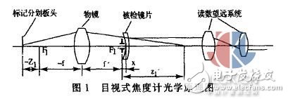
The power meter based on the principle of focusing imaging has a visual type (as shown in Figure 1) and a projection type [1]. The source of the measurement error is now illustrated by a visual example. From the optical imaging relationship, the value of the top power d of the inspected lens is obtained by the formula (1):
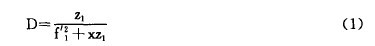
In Fig. 1 and (1), ç¾² is the distance between the reticle and the front focus f1 of the objective lens, f, 'is the back focus of the objective lens, and f1' is the focal length of the objective lens. When x=0, that is, f1' and the lens to be inspected The rear vertices coincide, and d is linear with z1. The intestine is a measurable value that is read by a displacement sensor that conforms to a linear relationship or a reading scale that moves in synchronization with the reticle to obtain a d of the apex power of the lens to be inspected.
A lens holder is used in the power meter and doubles as a diaphragm, which coincides with f'1. However, since the curvature (curvature) of the back surface of the lens to be measured is different, the shape is also concave, convex, and flat, so that the rear apex of the lens is separated from f'1, and the resulting x values ​​are different, and d in the formula (1) It is no longer linear with z1, thus causing measurement errors, and the error value increases as the lens's power value increases [2].
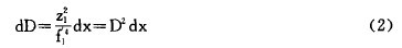
The equation (1) is differentiated and x is brought close to zero. The error value dd is given by equation (2) and increases rapidly with the square of d. Only the lens to be tested whose back surface is flat can ensure that the rear apex of the lens coincides with f'1 without error.
2. 2 automatic focus meter based on ccd and single chip technology
The optical principle of the automatic power meter is shown in Figure 2. In the figure, the spectacle lens is seated by a four-hole optical illuminator, illuminated by parallel light, and through the imaging objective lens, four image points are obtained on the ccd, and the spherical mirror, the cylindrical mirror, and the cylindrical mirror axis of the measured lens can be obtained. Position, prism degree and prism bottom direction.
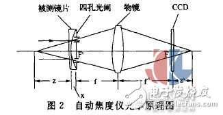
Let the four-hole aperture be distributed circumferentially with radius a, the focal length of the imaging objective is f', then the focal point coincides with the four-hole pupil, the front focus coincides with ccd, and b is the distance from the four pixels to the optical axis on ccd. . If the apex of the lens under test coincides with the back focus of the imaging objective (ie, x=0 in Figure 2), then z is the back top focal length of the lens and 1/z is the back apex of the lens (d). According to the optical imaging formula, there are:

Obviously, as long as the b value is measured, the d value of the measured lens top power can be obtained. However, if the back apex of the lens under test does not coincide with the back focus of the imaging objective, that is, x ≠0, the autofocus meter also produces measurement error, and the source and error of the error are the same as the power meter based on the focus imaging principle.
Correction method for measurement error of 3 power meter
According to further analysis, it is proved that when d is less than ±15 m-1, the test accuracy is acceptable; when d is larger than ±15m-1, the test accuracy is not enough; when it is less than 20m-1 and above, the accuracy is obviously reduced.
3.1 Hardware Correction
Improve the design of the power meter to ensure that the objective lens back focus f1' value is shown in Table 1.
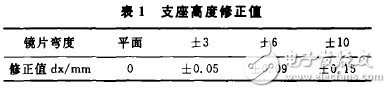
The support height correction value dx corresponding to the camber other than the table can be calculated by the formula (1).
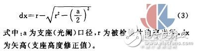
3. 2 software correction
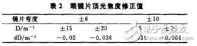
Without changing the height of the support, the dx of the different camber lenses is obtained according to the formula (3), and the correction table is prepared by the formula ((2) to find the relationship between dd and dx, which is corrected by the automatic power meter single-chip computer. If the support (Light) caliber a = 8mm, the correction value is shown in Table 2.
4 Conclusion
At present, there are many problems in the quality of spectacle lenses on the market in China. The reasons are related to measuring instruments and measurement procedures in addition to processing factors. The visual power meter based on the principle of focusing imaging and the automatic power meter based on CCD imaging and single chip technology are widely distributed in the market. The source of measurement error is clear, and the theoretical analysis and market test results are very good. Consistent, the problem is concentrated on the height of the number (d) 15m-1) on the glasses
10KW-200KW Three-Phase Inverter
10KW-200KW Three-Phase Inverter
CHARACTERISTIC
â—Online working mode design, high speed static switching..Superior load characteristics
â—Perfect protection function
â—High performance dynamic characteristicselntelligent battery management
â—Optional battery patrol module


Nkm Hybrid Inverter With Mppt Charge,Inverter Power Inverter,Hybrid Inverter Charger,Hybrid Grid Tie Inverter
suzhou whaylan new energy technology co., ltd , https://www.whaylan.com