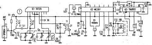
The following introduces a high-sensitivity FM radio suitable for weak signal areas and remote mountain areas, with a sensitivity of O. 5uV, the receiving effect of strong and weak stations is better. The machine uses a combination of high-performance radio circuits to form a double-conversion receiving circuit. The complete circuit is shown in the attached figure 1. F1 (BP8804) is a ceramic band-pass filter of 87 ~ 108MHz, and its center frequency is 97.3MHz. The shape is shown in Figure 20. V1 and R1, L1 form a high-frequency pre-amplifier, which can significantly increase the receiving sensitivity. The machine adopts the method of double frequency conversion to improve the image frequency suppression ratio, so that a multi-stage high-amplifier circuit can be added without interference from the image frequency.
ICl is a high-frequency head circuit TA7335 for FM, which includes high-amplifier, local oscillator, frequency mixing and other functions. The operating voltage is 2 ~ 6V. Pin ①is the signal input terminal; ② is the positive terminal of the power supply; ③ and ④ are high Put the circuit; ⑤ ground; ⑥ is the intermediate frequency output terminal; ⑦ is the local oscillator circuit; ⑧ is connected to the AFC voltage. IC2 is a MC3361 intermediate frequency amplifier circuit dedicated for FM receivers. It only needs a small number of external components to complete the functions of secondary conversion, intermediate amplifier, frequency discrimination, audio amplification and so on. The first intermediate frequency signal output from the ⑥ pin of ICl enters the 16 pins of MC3361, and is mixed again with the X3 (10.245MHz) signal, and the second intermediate frequency signal of 455kHz is coupled by X3, thus realizing the double conversion and the inductance of the circuit Can be homemade. If the BPB804 with thin-pass filter cannot be purchased, the circuit shown in Figure 2 (b) can be used instead.
The L0 in the picture is made of 0.5mm enameled wire wound on a 0.4mm round bar and rolled out 5 times; L1, L2, L3 wire and winding method are the same as L0, L1, L2 are 4T, L3 is 3T; T1, T2 are used Cap-adjusted intermediate frequency transformer restructuring; data shown in Figure 1, pay attention to the primary and secondary end of the same name when winding T1. CO is a variable capacitor commonly used in FM radio, the capacitance value is generally adjustable in 3--20pf. The whole machine debugging mainly adjusts L2 and L3 to enable a difference of 1O. 7MHz intermediate frequency signal, then please adjust T1, T2 to make the best sound positive, and if necessary, adjust the number of inductance turns to meet the debugging requirements.

Follow WeChat

Download Audiophile APP

Follow the audiophile class
related suggestion
The main difference between automatic search FM radio and ordinary FM radio is that it ...
![[Photo] Automatic search for FM radio](http://i.bosscdn.com/blog/20/06/41/5192050177.jpg)
'+ data.data.username +' '; dom + ='
What are IC Sockets?
Most of our everyday electrical devices contain integrated circuits (ICs) or chips which are installed on the printed circuit board (PCB). Most chips are soldered directly onto the board but sometimes they need to be interchangeable, or removed, and this is when an IC socket is used.
The IC socket fits onto the board and holds the chip, protecting it from heat damage which could be caused by soldering. Programmable chips are a great example where IC sockets are used, allowing removal for testing, programming or replacement due to failure.
IC (Integrated circuit) Sockets
IC Sockets connector is designed to provide a compressive interconnect between component leads and a printed circuit board (PCB). This connector is designed to provide a compressive interconnect between component leads and a printed circuit board (PCB). It simplifies the board design, enables simple reprogramming and expansion and easy repair and replacement, and offers a cost-effective solution without the risk of direct soldering. With a wide range of solutions for land grid array (LGA) and pin grid array (PGA) sockets, this connector features contact tip geometry optimized to reduce risk of contact damage during handling and package installation.
Antenk offer a comprehensive range of DIP, SIP and PGA sockets to suit most multiple electrical applications.
Types of IC Sockets
DIL /DIP– Dual in-line. These have two parallel rows of pins, available in various numbers to match the relevant IC and are normally very cost effective. A larger socket can be created by placing two smaller ones together, end-to-end, e.g. two 8-pins become 16-pin.
SIL/SIP – Single in-line. This socket has a single line of pins and are frequently used in smaller applications like resistor arrays or boards with short lead pins, such as a desktop computer. There are many different sizes and attributes available.
PGA – Pin Grid Array Sockets. Complex printed circuits are too valuable to risk direct soldering to expensive integrated circuits (ICs). Using a socket is the answer. The use of sockets offers advantages that prove cost effective and simplify board design.
DIMM – Dual In-line Memory Module. Random Access Memory (RAM) can be easily installed in computers or laptops using DIMM sockets. These are important components that help to ensure reliable connectivity. They have two separate rows of electrical contacts or pins on either side. It`s a general rule that the more pins the higher the RAM it supports. There are various pin sizes available.
SIMM – Single In-line Memory Module. These have a single row of pins which connect memory modules to circuit boards. They are space saving and can be installed at predetermined angles with positive polarisation to prevent memory modules from being inserted incorrectly. They are used mainly in older computers dating from the 1980s to late 1990s. Available in various sizes and number of pins.


IC Sockets Connector/Integrated Circuit Sockets Typical Applications
In notebook and desktop computers, LGA sockets feature a robust bolster plate for reliable connection to the microprocessor package while limiting PCB bowing during compression.
In servers, our mPGA and PGA sockets -- with custom arrays available in more than 1,000 positions --offer zero insertion force (ZIF) interface to the microprocessor PGA package and attach to the PCB with surface-mount technology (SMT) soldering. Antenk's IC sockets are designed for higher performance CPU processors.
IC Sockets,Ic Socket Connectors,Pin IC Socket,Pin IC Socket Connector,IC Sockets Adapters,IC Sockets & Plugs,Integrated circuit Sockets,IC Sockets and Headers
ShenZhen Antenk Electronics Co,Ltd , https://www.antenkelec.com