Solar semiconductor refrigeration air conditioning is a special cooling method based on the photovoltaic effect of solar energy, that is, through the "photo-electric-cooling" approach, and using the electric energy generated by solar cells to drive the semiconductor refrigeration device to achieve thermal energy transfer. Solar energy photoelectric conversion can not only match the thermoelectric cooling DC power supply mode, but also have a good time matching between solar radiation intensity and cooling demand. In addition, solar energy is clean, environmentally friendly, resource-rich, inexhaustible, and solar energy and semiconductor environment are friendly. Therefore, solar semiconductor refrigeration and air conditioning can create a high-quality green living space. This design is to use Hainan's unique natural conditions, based on low cost, gives the design method of solar semiconductor refrigeration air conditioning test device. This method has broad application prospects in Hainan and the tropics. One of the tasks of this project is to design the solar semiconductor air conditioning control system.
1 System configuration of solar semiconductor air conditioner
The solar semiconductor refrigeration system can be composed of five parts: a solar photoelectric conversion device, an energy matching numerical control device, an energy storage device, a semiconductor refrigeration device, and a system control device.
In the case of sunshine, the solar-to-electrical converter converts the solar energy that illuminates it into electrical energy, providing the necessary energy for the air-conditioning system. The energy output from the solar-to-electrical-to-electrical converter of this paper is in good agreement with the electrical energy required by the air-conditioning system, and other auxiliary energy or energy storage devices are needed in the absence of sunshine or sunshine, in order to output part of the solar-to-electrical-to-electrical converter. The electrical energy is stored and spared to ensure that the solar semiconductor air conditioning system can operate around the clock. The digital matching device can match the output impedance of the solar array with the equivalent load impedance, so that the energy transfer of the entire system is always in an optimal state, and the overcharge and overdischarge of the energy storage device are controlled.
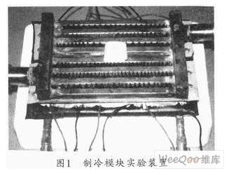
The semiconductor refrigeration and heating device usually consists of a plurality of thermopile or refrigeration units, wherein a heat sink is installed on both the cold end and the hot end. When cooling is required, the cold end is placed in the room to absorb heat to achieve the purpose of reducing the temperature of the cooling; the hot end is placed in the outdoor ventilation and heat dissipation. In the winter, when the ambient temperature is low and heating is required, the current direction through the thermopile can be changed by changing the positive and negative poles of the power supply. At this time, the cold end of the thermopile becomes the hot end and radiates heat to the room. The original hot end becomes the cold end to absorb heat from the surrounding environment, thus achieving the purpose of heating air conditioning. Figure 1 shows the experimental setup of the refrigeration module of this design.
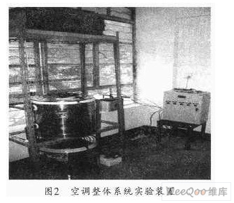
The control device of the system mainly has two functions, one is to adjust the indoor temperature and measure and control the temperature of the surface of the cold end of the refrigerating piece and the surface of the thermal conductive ceramic piece. The second is to adjust the indoor humidity, that is, to control a humidifying device. The system is not only automated and intelligent, but also provides the most comfortable environment for the interior. Its overall system test device is shown in Figure 2.
2 Air conditioning control system design
In the semiconductor refrigeration and heating device, the surface of the thermal conductive ceramic sheet on the cold end and the hot end of the refrigerating sheet can be coated with the idea of ​​thermal grease to reduce the contact thermal resistance. However, the thermal grease is more likely to melt when it exceeds 60 ° C. Therefore, it is necessary to know the ceramic surface at any time. The temperature, once it exceeds this temperature, requires fan cooling. In addition, the room temperature adjustment is set within a certain range (-10 ° C ~ 40 ° C), the user can adjust the temperature according to their own requirements, the accuracy can reach ± ​​0.5 ° C. In addition, the system can also detect indoor humidity, and can automatically adjust the humidity according to the comparison between the actual humidity and the set value. The man-machine dialogue interface is mainly used for setting the upper and lower limits of temperature and humidity and real-time display of temperature and humidity values.
3 hardware design
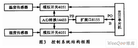
The system uses AT89C51 single-chip microcomputer produced by ATMEL Company, two DSL8B20 integrated temperature sensor produced by DALLAS Company, and capacitive humidity sensor HSll01 for hardware design. The system is divided into five parts: humidity acquisition, temperature acquisition, keyboard display, alarm display and execution output. Each part of the circuit takes AT89C51 single-chip microcomputer as the core, and the temperature, humidity or keyboard scanning signal is collected by the single-chip input/output port to the single-chip microcomputer. After being processed by the single-chip microcomputer, the input and output ports are output to the alarm display and the execution port for temperature. , automatic control and monitoring of humidity. The block diagram of its control system is shown in Figure 3.
3.1 Temperature collection
The PO.1 and P0.2 ports of the microcontroller are used as the data input and output ports of the temperature sensor. The temperature sensor DSl8B20 uses one-wire data transmission, so the system only needs one port to complete the input and output operation of the sensor. After the temperature sensor detects the analog temperature, it can be converted into 9 to 12 digits and stored in the scratchpad. When the temperature value is read, it can be read from the port PC5 under strict timing.
3.2 Humidity collection
HSll01 is actually equivalent to a humidity sensitive capacitor. Its oscillation circuit is composed of 555 timer. When the ambient humidity changes, the capacitance of the humidity sensor HSll01 will change accordingly. In this way, the capacitance value can be converted into frequency and by the oscillation circuit. The inverse square wave signal is transmitted to the microcontroller via PD3. The MCU can obtain the corresponding humidity value by frequency calculation.
3.3 keyboard display
CH452L is a keyboard display driver chip. Its pins DIN, DOUT, LOAD and DCLK are respectively connected with PB0~PB2 and PD2 of the single chip microcomputer. The system can set various parameters through the keyboard. The temperature and humidity values ​​collected by the single-chip microcomputer can also be displayed in real time through the digital tube.
3.4 Output Execution Port
The system can automatically detect the temperature and humidity values ​​and determine whether the temperature and humidity values ​​are outside the limits. If it is out of range, the PEO and PE1 output signals to control the actuator to adjust the temperature and humidity. In order to improve the stability of the system, an opto-isolator should be used between the MCU system and the execution unit to match the system and the field environment.
4 software design
After the microcontroller is powered on, the system should be initialized first. After the initialization is completed, it is judged whether the temperature and humidity upper and lower limits are set. If it is set, the setting parameter subroutine is entered. Otherwise, the temperature and humidity detection subroutine is entered. After the temperature and humidity detection subroutine is called, enter the temperature and humidity parameter display subroutine, and then judge the overrun. If there is an overrun, enter the alarm display and execute the subroutine. Otherwise, return to the initialization module and re-execute. The main program execution flow chart is shown in Figure 4.
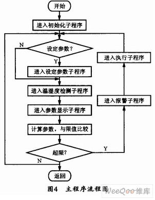
The main program of this design includes initialization module, temperature and humidity detection module, temperature and humidity parameter display module, alarm display module and execution module. The initialization module is responsible for calling the initialization system subroutine to initialize the relevant IO terminal and the timing counter; the temperature and humidity detection module is responsible for calling the temperature detection subroutine and the humidity detection subroutine, and the temperature detection program starts the temperature conversion from the initialization temperature sensor DSl8B20. After waiting for the conversion to be completed, the 9-bit binary code and the processed data are read and converted into corresponding temperature values; the humidity detection program calculates the frequency of the humidity signal from the initialization humidity sensor HS1101 and converts it into a corresponding humidity value. The temperature and humidity parameter display module is mainly responsible for calling the display parameter subroutine of the keyboard display driver chip CH452L. The CH452L display driver can start the display driver from the initialization CH452L, and enter the display program, and simultaneously send the temperature and humidity values; the execution module is responsible for calling The alarm display and execution subroutine, the execution program and the alarm display program start from the judgment of whether or not the limit is exceeded. As long as any one of the temperature and humidity exceeds the limit, the system enters the control execution program and the alarm display program.
5 Conclusion
Solar semiconductor air conditioners have the advantages of energy saving and no noise, which can meet the common needs of human beings. The solar semiconductor air conditioning control system introduced in this paper uses temperature and humidity sensors, and takes the single-chip microcomputer as the core. Therefore, the temperature and humidity monitoring system has high cost performance, simple use and stable and reliable operation. In fact, this control system can be applied not only to air conditioners, but also to greenhouses, grain storage and other temperature control, so it has certain promotion value. The test results also show that the system can detect the indoor temperature well and can automatically adjust according to the set temperature, and can automatically power off when over temperature, the reaction is very sensitive, and can achieve the intended purpose.
:
Air fryer is a common device in automatic control system. It is generally used for switching on and off circuits. It is an important component of automatic control and remote control circuits.
Air Fryer Relay,Low Power Air Fryer Relay For Home,Sealed Air Fryer Relay For Home,Miniatureair Fryer Relay
Ningbo Xingchuangzhi Electric Appliance Co.,Ltd. , https://www.xingchuangzhi.com