In response to the needs of the majority of friends, I will post this tutorial if you want to make a ZVS inverter. First, let’s get to know the circuit diagram
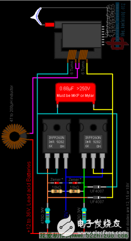
Among them, IRFP250 can be replaced by IRF3205, IRFZ44N and other N-channel field effect transistors, of course, the power is not the same. It is said that IGBT tubes can also be used. Why can't we use a triode? The reasons are as follows [the following non-original] (1) FET is a voltage control device, which controls ID through VGS;
(2) The input current of the field effect tube is extremely small, so its input resistance is very large.
(3) It uses majority carriers to conduct electricity, so its temperature stability is better;
(4) The voltage amplification factor of the amplifying circuit composed of it is smaller than the voltage amplification factor of the amplifying circuit composed of a triode;
(5) The field effect tube has strong anti-radiation ability;
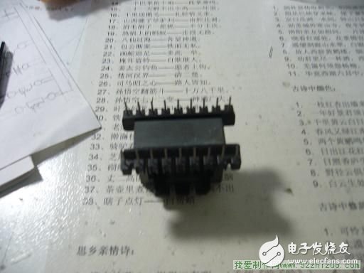
(6) Since there is no shot noise caused by chaotic minority carrier diffusion, the noise is low. In addition to FETs, capacitors are also a concern. This capacitor can be connected in parallel with two safety capacitors 0.3 microfarads, preferably a 1200V induction cooker capacitor. When using CBB capacitors, you must pay attention to the withstand voltage, because it is said that many people use CBB capacitors to easily break down. There is another problem that needs to be paid attention to that is the symmetry of the two windings of the transformer, that is, the number of turns of the two windings of the primary coil is as equal as possible. In addition, due to the high oscillation frequency of ZVS, iron cores composed of silicon steel sheets cannot be used, but magnetic cores must be used. Of course, the easiest thing is to use the high pressure coil directly. This is the core used
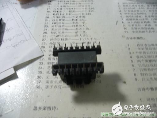
It can be disassembled in many switching power supplies or can be purchased online. Each EE35B core is about 2 yuan. Of course, enameled wire is also essential. I used the transformer primary 3 strands 0.8 enameled wire 3 plus 3 turns, secondary 0.5 enameled wire 50 turns, I did not calculate the power, everyone try it, after all, practice can test the truth. Because the battery is out of power, the renderings can't be uploaded this time. The idea of ​​making this inverter was seen on the Internet. I used two binding posts instead of two FETs. After all, FETs are easy to break. Group photo of all materials
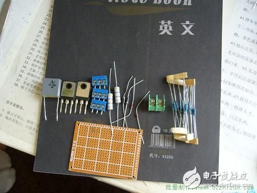
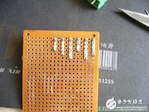
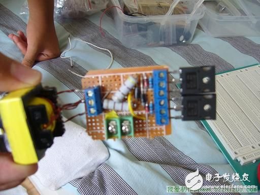
Among them, I used a finished inductor for the inductor. You can use an enameled wire with a diameter of about 1.0 to make 20 turns on the magnetic ring. As for some people who can’t understand the circuit diagram, let me talk about the connection method, say the GDS pole of the FET [from left to right] as 1, 2, and 3: Each FET's 1, 3 pins are connected to a 10K The resistor and a 12V voltage regulator tube, the negative pole of the voltage regulator tube is connected to pin 1, and the positive pole is connected to pin 3. The pins of the two fast recovery diodes are connected respectively: one of them is connected to pin 1 of the first field effect tube and pin 2 of the second field effect tube, the negative pole is connected to pin 2 of the second field effect tube, and the positive pole is connected to pin 2 of the second field effect tube. Connect to pin 1 of the first FET. The other is connected to pin 2 of the first field effect tube and pin 1 of the second field effect tube. The cathode of this Fast Recovery Diode is connected to pin 2 of the first field effect tube, and the anode is connected to the second field effect tube. Pin 1 of the tube. So far, the fast recovery diode is connected. Connect one end of the two 470 ohm 3 watt resistors to pin 1 of the two field effect transistors, and connect the other ends of the two resistors to the positive pole of the power supply. Connect the 3 pins of the two FETs together and connect to the negative pole of the power supply. A capacitor is connected in parallel between the 2 pins of the two FETs, and the 2 pins of the two FETs are connected to both ends of the primary coil of the transformer, and an inductor is connected in series between the tap of the primary coil and the positive power supply. This is all the wiring method. If you still don’t understand this, learn the basics of electronics. Here are some photos, this is half of the soldering
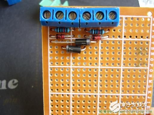
Cable on the back
Compare with my other ZVS after finishing
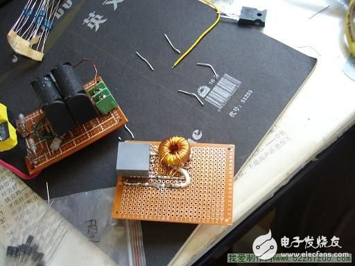
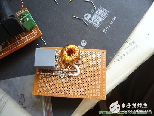
Load into the venue
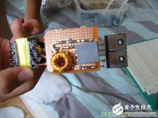
Connect the transformer

China leading manufacturers and suppliers of DC Support Capacitors,DC Capacitor, and we are specialize in Electrolytic capacitor,High Voltage Capacitor, etc.DC Support Capacitors
DC Support Capacitors,DC Capacitor,Electrolytic Capacitor,High Voltage Capacitor
YANGZHOU POSITIONING TECH CO., LTD. , https://www.cnchipmicro.com