Bionic robotic fish experimental platform belongs to a project of “national university student innovation experiment plan†jointly funded by the Ministry of Education and Beijing University of Posts and Telecommunications. It is an experimental platform integrating light, machine, electricity, fluid and intelligence. The research content includes: : Research on mechanical structure of bionic robotic fish, research on recommended efficiency and research on control performance.
1. Bionic Robot Fish Platform Introduction:
The robot fish designed and manufactured was designed to resemble the shape of the carps, and the head was made of a rigid structural plastic material. Its shape is streamlined, simulating the shape and size ratio of fish heads. In the inner space of the fish head, a power supply and control circuit are installed. Three infrared sensors are installed at the fisheye on both sides of the fish head and on the lower side of the front of the head to form a detection of left, front and right directions. The sensor network allows the fish to have a self-service obstacle avoidance function.
The fish skeletons made of aluminum alloy are used to connect three servos in series. The skeleton of the fish supports the rubber skins on the outside of the steering gear, which constitutes the three-joint drive system of the robotic fish. Connections made of aluminum alloy are used to fasten the fish to the rigid head by means of a threaded connection. The rubber skin of the fish is glued to the head using hot-melt glue, which constitutes the overall result of the robotic fish. Specifically as shown in Figure 1. Experiments have shown that this method is simple and easy to disassemble and assemble.
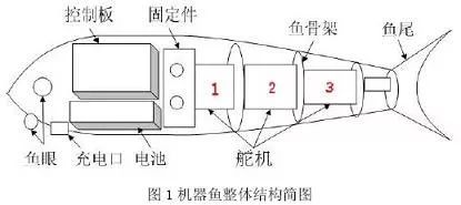
Robotic fish technical indicators: parade speed: 1.2~1.5m./s; full battery parade distance: 4.5~5.5km; turning radius: 15~20cm.
2. System composition and working principle:
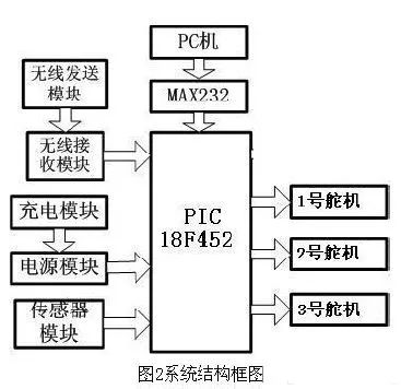
From a functional point of view, the entire fish system can be divided into three blocks, namely: perception zone, decision zone, and behavior zone. The sensing area corresponds to a multi-infrared sensor network and an infinite transmission module, and the decision area refers to a main control chip (MCU), and the action area corresponds to a three-joint drive system consisting of servos connected in series. Specifically as shown in Figure 2. The most important work of this system is focused on the coordinated control of multiple servos. Therefore, a detailed and detailed introduction on the control work of the servos is mainly carried out.
3 Servo Control
3.1 The working principle of steering gear:
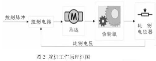
The servo mainly consists of the following parts: rudder plate, reduction gear set, proportional potentiometer (position feedback potentiometer), DC motor (motor), control circuit board, etc. Its working principle: the control circuit board receives the control signal from the signal line, controls the rotation of the DC motor, and the DC motor drives a series of gear sets. The output shaft of the gear set is connected with a linear proportional potentiometer, and the potentiometer turns the output shaft. The over-angle θ converts the proportional voltage feedback to the control circuit. The control circuit compares it with the input control pulse signal, generates a correction pulse, and drives the motor to rotate forward or reverse so that the output position of the gear set matches the expected value. , so that the correction pulse tends to be 0, so as to achieve the purpose of positioning the servo accurately. The servo is a typical closed-loop feedback system. Its working principle is shown in Figure 3.
There are three input lines for the servo, the middle of the red line is the power line, and the black line is the ground line. These two lines provide the steering gear with the most basic energy guarantee, mainly the motor rotation consumption. The power supply has two kinds of specifications, one is 4.8V, one is 6.0V, corresponding to different torque standards, and the other line is the control signal line, generally white.
3.2 Angle control of single steering gear and multiple steering gears
3.2.1 angle control of single steering gear:
According to the working principle of the servo, a period pulse signal with a period of about 20 ms and a pulse width between 0.5 ms and 2.5 ms is input to the servo, which drives the servo output shaft to reach a rotation angle between -90° and 90°. , a linear change. And no matter how the external torque changes, the servo output shaft will remain at a corresponding angle until it is given a pulse signal of another width, it will change the output angle to the new corresponding position. Through programming, with the output port of the microcontroller to obtain the required periodic pulse signal.
Program example: (Crystal: 4MHZ, pulse output from PORTDbits.RD0)
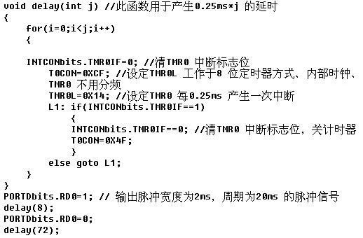
As can be seen from the above procedure, by changing the parameter j of the delay function, a pulse signal having a corresponding pulse width and period can be obtained as required. For example, change the 1 to 4 behavior of the above program segment:
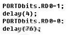
A pulse signal with a pulse width of 1 ms and a period of 20 ms is obtained. Then, with the aid of a for loop, the desired periodic pulse signal will be obtained, which will drive the servo output shaft to a rotation angle between -90° and 90°.
3.2.2 Control of multiple servos at different angles:
Through the control of multiple servos at different angles, several servos can be controlled to be twisted at different angles at the same time so as to achieve the desired control purpose.
The specific implementation method is to set a timer value t in the timer delay function (the value of t is 0 in the program during initialization), so that t is incremented each time the timer is finished. For example, if the timer's one cycle time is 0.25ms, then each value of t increases by 0.25ms. When the representative value of t reaches 20ms, that is, when t is equal to 80, the pulse period can be controlled to 20ms. By using the if statement query mode, the pulse width of the same period pulse can be adjusted, that is, multiple servos can be enabled. At the same time rotate to different angles.
Program example: (Crystal: 4MHZ, pulse output from PORTDbits.RD0, PORTDbits.RD1, PORTDbits.RD2 three ports)

Through the above program and then with the for loop, three periodic pulse signals with pulse widths of 1 ms, 1.5 ms, 2 ms, and the same period of 20 ms can be obtained at the three ports PORTDbits.RD0, PORTDbits.RD1, and PORTDbits.RD2. Different servo control requirements for the three steering gears. Of course, using the above method, it is very easy to simultaneously control more than three servos.
3.3 Servo Speed ​​Control
Through the characteristics of the servo, it can be understood that the instantaneous movement speed of the servo is determined by the cooperation of the internal DC motor and the transmission gear set. The value is constant under constant voltage driving. However, the servo's average movement speed can be changed by the control method of step-by-step pause. For example, subdividing the rotation with the 90 degree movement into 128 pause points, and controlling the time of each pause point to achieve 0° to The average speed of 90° changes. That is to say, the 90 degree continuous one-step rotation is changed to 128 pause step rotations, and the purpose of deceleration can be achieved by a short pause between each step, because the pause time is very short and therefore can be considered as a 90 degree continuous rotation. , Due to space limitations, no corresponding program examples are given here. Interested readers can refer to the above examples for programming.
4. Conclusion
The PWM waveform generated by this method introduced in this paper has high accuracy, and it can well complete the servo control work. The servo is stable in operation. The robotic fish we designed and manufactured successfully achieved some basic movements of fish, such as , Acceleration, stop, forward turn, etc. This also verifies that the adopted multi-joint drive method and control method for multiple servos are effective. This article intends to initiate an article by using the bionic robotic fish as a carrier, and hopes to help other servo control applications.
Molded Waterproofing Cable Assemblies
We specialize in waterproofing products overmolding. We can custom build, custom mold, and over-mold your cable designs.
We specialize in molded cable manufacturing for the widest diversity of
cable and connector types, across the whole spectrum of industries. Rich expeirence in developing and proposing solution Special for IP67, IP68 waterproofing products.
Molded waterproofing cable assemblies, waterproof wire harness, waterproofing cables overmolding
ETOP WIREHARNESS LIMITED , https://www.oemwireharness.com