In the field of measurement and instrumentation, the measurement of digital signals is mainly to measure the pulse width of the signal. At present, the most used method is the pulse counting method, that is, the high-frequency clock pulse is used to count the low level or high level of the signal to be tested, and then the signal width is obtained by calculation according to the number of pulses. The signal is independent of the counting clock, and the rising and falling edges of the signal cannot exactly match the clock edge, so the maximum error obtained by this method can reach one clock cycle. For example, if the high frequency clock is 80MHz, then the maximum error amount can reach 12.5ns.
The precision of pulse counting method can also be improved in an effective way. The measurement error will decrease with the increase of the clock frequency, but as the frequency increases, the requirements for the chip will increase relatively. For example, if the measurement error is required to be 1ns, the clock frequency must reach 1GHz, and the general counter chip cannot work normally in this state, and the circuit board wiring, processing and material selection will become difficult problems. The use of time-amplitude conversion technology does not require the clock frequency, but this method uses an analog circuit. If the frequency to be measured is relatively high, the measurement result is easily disturbed by noise, and if the requirement is the signal pulse width For continuous measurement, whether the circuit can respond quickly is a major drawback that needs to be solved in this method.
What is different from the above two methods is that the article discusses a new method, which improves the measurement accuracy of pulse width by means of digital phase shifting. This method adopts FPGA chip to realize high-precision pulse width measurement.
1. Measurement principle
The two channels of the same frequency signal take one channel as a reference, and the other channel takes the signal of this channel as a reference to perform lag or advance movement to form a corresponding phase difference, which is phase shift here. This measurement method usually uses a delay method, which is determined by the length of the delay by determining the phase difference generated between two digital signals. The basis of this measurement principle is digital phase shifting technology. The original count clock signal CLK0 is phase-shifted to obtain CLK90, CLK180, and CLK270. The phases are separated by 90° in turn, and the four identical counters are simultaneously driven by these four clock signals to complete the signal counting.
2. System implementation
The phase difference between the counting clocks is the basis for the system to maintain normal operation. The original clock frequency usually has a higher frequency, the frequency is connected to 100MHz, and the period is greater than 10ns and less than 20ns, so even if there is a delay time, It is only a few ns; in addition, in order to avoid adverse effects on the circuit board chip due to transmission delay, the flexibility of the system as well as stability and accuracy must be guaranteed. The article realizes the measurement method through the programmable gate array. It can be seen from the analysis of the following figure that the measurement results are finally sent to the FIFO buffer, so that the processing speed can be effectively improved, and finally the data transmission is completed through the PLC bus.
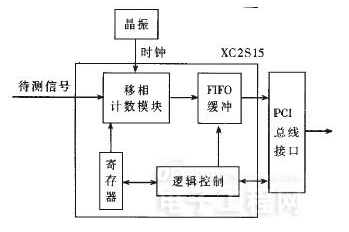
The sequence between each module needs to be coordinated and controlled, and through the logic control, the time can be effectively obtained and the system can run normally. The FIFO buffer module is implemented in the FPGA chip, and the logic control is also implemented in the chip.
The artanII series is relatively cost-effective compared to other FPGA chips. And the highest operating frequency has reached 200MHz. Here, the chip uses XC2S15-6 to ensure that the clock signal will not be always external and delayed transmission; and it is relatively convenient to control the clock signal, such as the frequency division of the clock signal. As well as frequency doubling and phase shifting. In addition, the DLL function can realize the rapid construction of the phase-shift counting module, so as to realize the several measurement methods introduced in the above article. The original clock processed by the DLL can obtain four groups of phases with a difference of 90°, namely SLD0, CLK90, CLK180 and CLK270, and finally calculate the signal pulse width value.
3. Simulation analysis and precision analysis
By giving the internal wiring, the target result of the chip is realized, and the simulation result is realized by Modelsim. After RESET, start the counting module, and then start to measure the signal to be measured. After the measurement, a READY signal will be generated. At the same time, the measured result will be output to provide basic information for subsequent measurement calculation and analysis. It can be proved through simulation experiments that the system can achieve target requirements.
Then further error analysis of the system is carried out. The main reason for the error of the system measurement pulse width measurement is the existence of multiple errors such as system principle error TS, clock phase shift error Tp, signal delay error Td and counting clock jitter Tc. It can be seen from the above analysis that if the crystal oscillator is 80MHz in the clock input process, the error amount obtained is 3.125ns. The clock phase shift error is the signal itself generated by the four-way phase-offset. The signal is separated from the SLKDLL. According to the chip parameters, the maximum phase shift error can reach 200ps.
The results can be obtained through analysis and calculation: the delay time from the counting clock to the respective counters can be obtained respectively, and the time from the HF signal that controls the start and stop of the counters to the four counters. Since what is required is the relative delay time between the count clocks, the delay of the clock relative to the HF signal to the counter can also be obtained.
Digital phase-shifting technology is the basis of our current application in pulse width measurement. On this basis, this paper proposes a higher-precision measurement system. This method is different from the pulse counting method, and its accuracy is even higher than that of pulse counting. Count multiple times. The measurement accuracy of this method can continue to be improved, mainly through the following two aspects: first, continue to increase the frequency of the crystal oscillator, and increase the speed of the FPGA chip faster. It is also because the principle error of the system will be affected by the frequency of the crystal oscillator. The higher the crystal oscillator frequency, the smaller the error value will be. The second is to reduce the signal delay error. It can be seen from the previous analysis that the system accuracy will be affected by the signal delay error. The measurement accuracy can be effectively improved by reducing the signal delay difference of the counter and the technical clock. In addition, in the FPGA chip, the signal delay time can be easily obtained. Therefore, the delay error can be adjusted only by adjusting the position and wiring of the internal components in the design process, or by adding some gate circuits, so that the signal The delay time remains the same.
Roll Type Condenser
Roll bond evaporators are widely used on refrigerators and Freezers.Evaporator of roll bond are made of two aluminum sheets assembled by a rolling process. Pressurizing the panel to create the channels.There are One Side flat china roll bond evaporator ,Double side inflated roll bond evaporator ,Partial one side flat roll bond evaporator. End of inlet/outlet tube , it is joined with copper tube , which is easy to connect with the whole refrigeration system . Surface of the roll bond evaporator is painted with plastic powder .
Freeze Condenser,Roll Type Condenser,Fridge Condenser Coils,Cold Room Condensing Unit
FOSHAN SHUNDE JUNSHENG ELECTRICAL APPLIANCES CO.,LTD. , https://www.junshengcondenser.com