Before talking about the international standards and national standards of the grounding system, let's first understand the power transformer, as shown in the following figure:
The picture on the left is a physical picture of the internal wiring of the power transformer. We see four groups of tinned copper bars in yellow, green, red and blue, these four groups of copper bars are L1, L2, L3 three-phase windings and neutral line N respectively.
The picture on the right is the wiring diagram. We see the L1, L2, L3 three-phase windings, as well as the neutral wire N, and the yellow-green ground wire PE.
The wiring diagram on the right has a name called the wiring system of the low-voltage distribution network.
It is worth noting that the three-phase in the wire system is the three-phase winding of the transformer, and the "wire" in the wire system refers to the line through which current flows during normal operation.
my country's national standard GB156-2009 "Standard Voltage" stipulates that the voltage at the outlet of the low-voltage side of the power transformer, the phase-to-phase line voltage is 400V, and the phase-to-neutral line voltage is 230V.
The three-phase winding has current flowing during normal operation, so the line where the three-phase winding is located conforms to the "line" regulations; the neutral line also has three-phase unbalanced current flowing during normal operation, so the neutral line N also conforms to the "line" requirement. â€; the ground wire PE has no current flow during normal operation, so it does not belong to the “wireâ€.
Therefore, the wire system shown in the above figure is called a three-phase four-wire system. If some people think that this wire system is a three-phase five-wire system, this kind of understanding does not conform to international standards and national standards, please correct yourself.
Now, let's get to know a very important IEC standard about grounding system - IEC60364:1. The national standard corresponding to this standard is GB16895.1 "Low-voltage electrical installations_Part 1: Scope, purpose and basic principles". This standard specifies the grounding form of low-voltage distribution networks.
In IEC60364, the grounding system is represented by two connected characters.
The first character represents the working grounding on the power supply side: if the neutral point of the transformer is equipped with a working grounding, it is called T;
The second character represents the protective grounding on the load side: if the exposed conductive part of the load side is directly grounded, it is called T, and if the exposed conductive part of the load side is not directly grounded, it is called N.
According to different wire systems, IEC60364 provides three grounding forms, TN, TT and IT. TN is further subdivided into TN-C, TN-S and TN-CS.
Now, let's take a look at what each of these grounding forms look like.
(1) TN-S grounding system
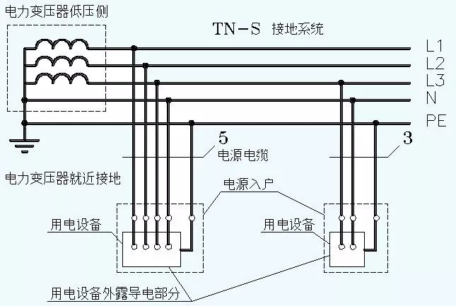
Let's look at the power transformer first, and we find that its neutral point is directly grounded, that is, it is equipped with a working ground, so the first letter is T.
We saw that after the neutral point of the power transformer is grounded, it is separated into two lines of N and PE, and after it is led out, the N and PE must be insulated.
The second letter is N because the exposed conductive parts on the load side of the TN-S are not directly grounded.
It is worth noting that:
The PE line must not be disconnected under any circumstances. Once the PE line is disconnected, personal injury will occur after the load shell is electrified. Therefore, the PE line of the TN-S grounding system can be grounded repeatedly at multiple points. However, after the PE line and the N line are separated, it must be ensured that the two will not merge again.
The N line can be disconnected. Therefore, under TN-S, a 4-pole switch can be used to combine and divide the N line.
In the three-phase system of TN-S, the number of cable cores is 5; in the single-phase system of TN-S, the number of cable cores is 3. Probably, this is also the reason why people are used to calling the TN-S grounding system "three-phase five-wire system".
TN-S grounding system is widely used in enterprises and institutions.
(2) TN-C grounding system
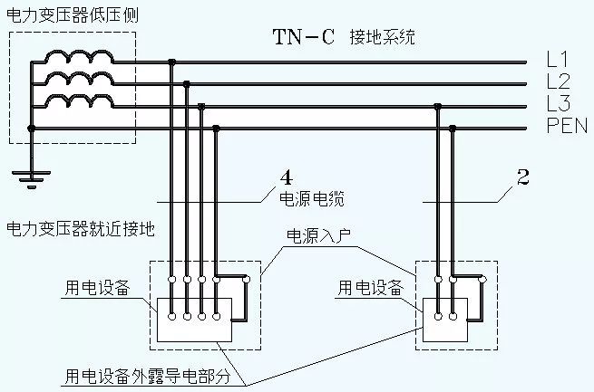
Let's look at the power transformer first, and we find that its neutral point is directly grounded, that is, it is equipped with a working ground, so the first letter is T.
We see that after the neutral point of the power transformer is grounded, it is led out in the form of PEN. The PEN line has a very famous name called the zero line. Correspondingly, the phase wire is also called the live wire.
Interestingly, too many people refer to the N line as the zero line. But I don't know that the zero line is not allowed to be cut off.
The exposed conductive parts on the load side are not directly grounded, so the second letter is N.
It is worth noting that since the PEN line is mainly for protection, in the TN-C grounding system, the PEN line must not be disconnected under any circumstances. Once the PEN line is disconnected, personal injury will occur after the load shell is electrified. Therefore, the PEN line of the TN-C grounding system must be grounded repeatedly at multiple points.
Under no circumstances shall the TN-C grounding system use a 4-pole switch to switch PEN lines. Similarly, for the single-phase two-wire TN-C system, the PEN line, that is, the zero line, is not allowed to be cut off, and the PEN line is absolutely not allowed to enter the switch.
In the three-phase system of TN-C, the number of cable cores is 4; in the single-phase system of TN-C, the number of cable cores is 2.
The TN-C grounding system shall not be used in flammable and explosive places such as oil depots, ports, airports, and mines.
(3) TN-CS grounding system
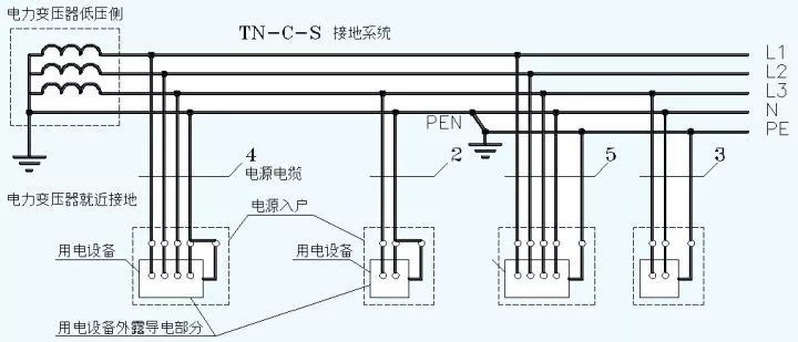
The first half of TN-CS is the TN-C grounding system, and the second half is the TN-S grounding system.
We see that the PEN wire is grounded again in the middle and then split into N and PE. From then on, N and PE cannot be merged again.
TN-CS grounding system is the main force in home power distribution.
It is worth noting that there is a neutral PEN in the first half of the TN-CS, which is not allowed to be cut off. The second half of TN-CS has no neutral line PEN, only N line and PE line. Here, the N line can be cut off, so a switch such as 1P+N is used for the main incoming line.
However, the PE line here is not allowed to be cut off. If the PE is cut off, it will cause serious personal injury.
Now, let's see what are the common characteristics of TN systems:
We already know that the TN system has a working ground, so once a single-phase ground fault occurs in the TN system, the fault current returns to the power supply through the PEN line or the PE line, and its current is approximately equal to the short-circuit current relative to N. Therefore, the TN system is also known as the high-current grounding system.
Let's look at the picture below:
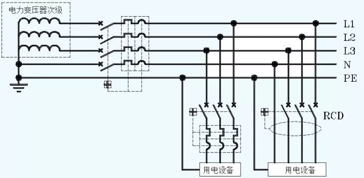
This diagram is a typical TN-S grounding system. We see that the main incoming circuit breaker is 4-pole, and is equipped with overload protection and short-circuit protection. Overload protection and short circuit protection are collectively referred to as overcurrent protection devices.
Pvc Conduit Pipe,Plastic Conduit Pipe,Electrical Wiring Pipe,Plastic Cable Conduit
FOSHAN SHUNDE LANGLI HARDWARE ELECTRICAL CO.LTD , https://www.langliplastic.com