Focus on the basic structure and related knowledge of DCS from the professional perspective of the manufacturer, and provide knowledge of DCS selection principles, precautions, and main selection indicators. Focus on the practicality and specific operability of knowledge. At the same time, it supplements the development history and development trend of DCS. Provide learning materials for engineers and technicians to understand the different characteristics and advantages of each system.

1 DCS system definition
DCS is the abbreviation of Distributed Control System. Chinese is used to be called distributed control system. It is a multi-level computer system composed of a process control level and a process monitoring level, which is a communication network. It integrates 4C technologies such as Computer, Communication, Display (CRT) and Control (Control). The basic idea is decentralized control, centralized operation, hierarchical management, flexible configuration, and convenient configuration.
The world's first DCS system was launched by Yokogawa Corporation (YOKOGAWA) in 1975 and was tried at the industrial site.
China's DCS system started relatively late. The domestic HOLLYSYS company first introduced the first domestic DCS system HS1000 in 1993, and gradually applied and promoted it on the industrial site.
2 The main structure and characteristics of the DCS system
·The system mainly consists of on-site control station (I/O station), data communication system, man-machine interface unit (operator station OPS, engineer station ENS), cabinet, power supply and so on. The system has an open architecture that provides multiple layers of open data interfaces.
·The hardware system has high reliability, convenient maintenance and advanced technology in the harsh industrial field. The underlying Chinese software platform has powerful processing functions, and provides convenient ability to configure complex control systems and user-developed special advanced control algorithms; easy to configure and easy to use. A variety of fieldbus standards are supported to accommodate future expansion needs.
• The system is designed with appropriate redundancy and diagnostics to module-level self-diagnostics for high reliability. Failure of any component in the system will not affect the operation of the entire system.
· System parameters, alarms, self-diagnosis and other management functions are highly concentrated on the CRT display and printed on the printer. The control system is truly functionally and physically dispersed. The DCS system is at least 99.9% usable. The failure time is 100,000 hours, and complete monitoring of nuclear power, thermal power, thermoelectricity, petrochemical, chemical, metallurgy and building materials has been realized.
· The concept of "domain". The large-scale control system is divided into a number of relatively independent sub-systems by a high-speed real-time redundant network. One sub-system constitutes a domain, each domain shares management and operation data, and each domain is a fully functional DCS system, so as to better Meet the user's use.
· Network structure reliability, openness and advancement. In the system operation layer, redundant 100Mbps Ethernet is used; in the control layer, redundant 100Mbps industrial Ethernet is used to ensure system reliability; in the field signal processing layer, 12Mbps PROFIBUS bus is connected to the central control unit and each field signal. Processing module (I/O module).
· Standard Client/Server structure. Some DCS operating layers use the Client/Server structure.
An open and reliable operating system. The operating layer of the system uses the WINDOWS NT operating system; the control station uses the mature embedded real-time multitasking operating system QNS to ensure the real-time, security and reliability of the control system.
· Standard control configuration software. The system adopts the control configuration tool of IEC61131-3 standard, which can realize any monitoring and control requirements.
· Scalability and tailorability to ensure economy.
2.1 Network Architecture
Generally, the network architecture of the DCS system consists of three parts (excluding the field instrument layer). From top to bottom, it is the management network (MNET), the system network (SNET), and the control network (CNET). The system network and the control network are both redundant configurations, and the management network is an optional network. The system network architecture is shown in Figure 4-1-1.
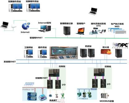
Figure 4-1-1 Typical network architecture diagram of DCS for distributed control system
·Management Network (MNET)
It is composed of 100/1000M Ethernet network and is used to control the system server to communicate with the plant-level information management system (Real MIS or ERP), INTERNET, third-party management software, etc., to realize advanced management and sharing of data. The management network layer is an optional network layer.
·System Network (SNET)
It is composed of 100/1000M high-speed redundant industrial Ethernet network, which is used for the connection of engineering station, operation station, field control station and communication control station, and completes the data download of the field control station. High-speed redundant safety network capable of quickly building star, ring or bus topology, conforms to IEEE802.3 and IEEE802.3u standards, based on TCP/IP communication protocol, communication rate 100/1000Mbps adaptive, transmission medium is Category 5 twisted pair with RJ45 connector.
·Control Network (CNET)
Use redundant fieldbus to connect to individual I/O modules and smart devices. Real-time, fast and efficient completion of communication tasks with the field, the transmission medium is shielded twisted pair or fiber optic cable.
2.2 System components
The system is mainly composed of engineering station, operator station, historical station (optional), control station and other components; and the network node of the control network is composed of control station and I/O module.
·Engineering station
Used to complete system configuration, modification and download, including: database, graphics, control algorithm, report configuration, parameter configuration, configuration configuration of operator station, field control station and process I/O module, data download And incremental downloads, etc.
·Operator station
Used for monitoring and management of production sites, including: centralized management and monitoring of system data, process flow chart display, report printing, control operations, historical trend display, log, alarm recording and management.
·Historical station (optional)
Used to complete system historical data services and exchange information with the factory management network. Typically, it needs to be configured separately in a large system, and a small system can take care of the operator station.
·Control station
Used to perform on-site signal acquisition, control and interlock control algorithms, control output, and transfer data and diagnostic results to the operator station via the system network.
·I/O module
Used to convert analog signals to digital signals, engineering unit transformations, module and channel fault diagnostics. It is sent to the main controller unit via a redundant multi-function bus.
3 Main considerations for DCS system selection
3.1 System overall design selection
At present, the design concept of DCS system is a combination of high reliability and high availability; all core components support redundant design.
The overall design is divided into two genres in the hardware structure: centralized board and distributed modules.
Concentrated board type: The cabinet is first installed with the cage, and the I/O module is inserted into the cage in the form of a board. The priority of this type of installation is that the seismic performance is good, and multiple devices are conveniently arranged on the circuit board, so the number of channels is large. The disadvantage is that it is limited by the cage and the installation is not flexible. Because it is necessary to control the arrangement of the terminal blocks, the occupied space is large, and only the arrangement of the card members can be proved, and the terminal block plates are arranged on the reverse side, and a special cabinet is required.
Decentralized modular: The cabinet does not require a cage, and the I/O modules are installed in the cabinet as separate modules. The advantage of this installation method is that it is flexible and convenient to install in any space, occupying small space and good heat dissipation. The shortcomings are lower than the board type. Due to the small size of the module, the number of channels is limited.
With the development of electronic components, miniaturization and intelligence are the development trend, and the modular type has increasingly shown the advantages of flexibility and change, and the board type has been phased out. Therefore, YOKOGAWA and Honeywell have completed the transition from large board type to small module type, ABB full range. Emerson's DeltaV, Invensys' I/A, Ovation, etc. all use a decentralized module structure. The latest K-series of the domestic Hollysys and the ECS700 of Zhejiang Zhongkong use a decentralized modular structure.
The overall design is divided into two genres in the software structure: peer-to-peer network structure (P/P) and client/server C/S structure.
Peer-to-peer network structure (P/P): The control station is equal to the status of the operator station, and the communication method is point-to-point. The advantage is that the communication does not depend on the communication node, and the danger is relatively dispersed. The downside is that the size of a domain's system is limited. The amount of data processing is also limited. It is difficult to adapt to very large-scale system structures such as nuclear power.
Client/Server C/S Structure: Communication between the controller and the operator station communicates through the server node. The advantage is that it is advantageous for large and very large systems. The disadvantage is that communication relies on redundant server nodes and requires high reliability.
Given the advantages of peer-to-peer (P/P) and client/server C/S architectures, state-of-the-art systems are hybrid architectures that are supported by both communication architectures and can exist in a single system. Such as Honeywell's PKS-C300 series and Hollysys' MACS-K series. It can be dangerously dispersed and adaptable to large scale.
3.2 Hardware selection
1) Controller
The considerations for controller selection are mainly response period, module capability and expansion capability. The computation cycle determines the response speed required for the device; the capability of the module determines the size of the system; the scalability determines the ability to interface with third-party instruments.
2) Response period
The response period of the controller includes two parts: the sampling period and the operation period. The sampling period depends on the I/O module sampling speed and the I/O module bus speed. The calculation cycle depends on the CPU operation speed. Advanced controllers typically have the ability to set different computation cycles to meet control needs. Usually 100ms, 200ms, 500ms, 1000ms, 2000ms are optional. Different control objects can use different calculation cycles, which is an important indicator to measure whether the controller technology is advanced.
Selecting the controller's operation speed can't just look at the CPU's main frequency. Because of different system architectures, the efficiency of system operation is quite different. At present, there are mainly PowerPC, ARM and X86 architectures. The X86 architecture CPU has a high frequency, but the computational efficiency is not necessarily high. The same architecture uses RISC (Reduced Instruction-Set Computer) instructions compared to CISC (complex instruction set). Computer) instructions are more efficient.
For the conventional control loop, the cumulative response period from IO through PID operation to AO output can reach the third speed of 250ms, 500ms and 1000ms, and the controller should have fast control capability, from IO through PID operation to accumulation of AO output. The response cycle can be as fast as 120ms.
3) With module capability
The capability of the module determines the scale of the single control station system. Most DCS systems are in the range of 60~120. The number of single module points in the market is 8/16 points and the switch quantity is 16/32 points. The capacity of a single control station is around 600-1200 points. The capability of the module with the control response speed is a contradiction. When the response time is short, the number of modules needs to be reduced accordingly. In particular, limit the number of fast control loop modules. Generally, the controller load is not more than 50% as the final requirement.
4) Expansion ability
Where fieldbus instrumentation is required, the controller is required to have the capability of third-party bus instrument access. Currently, the DP bus, PA bus, Modbus bus and FF bus are more common. This requires the controller to have the ability to hang the gateway bus module.
Controller redundancy is a must for DCS selection. The time for redundant switching is generally less than 2ms. This is easy for modern electronic technology. The fast and accurate diagnostic circuit determines the switching time. However, the uninterrupted switching of the software directly affects the field devices, so the bumpless switching of the software output data is the key technology to measure the controller redundancy technology. The general requirement is no more than the minimum control period. Therefore, the data synchronization technology of the two controllers is the key to ensuring bumpless switching. The redundancy principle of the DCS controller is shown in Figure 4-1-2.
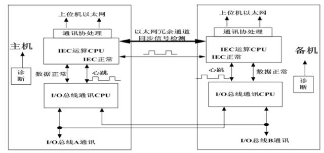
Figure 4-1-2 Schematic diagram of DCS controller redundancy
5) Communication network
The communication network between the controller and the HMI operating station is generally a redundant network of Ethernet. The communication rate is 100/1000 Mbps. The network between the control station and the internal I/O module generally has a custom redundant bus, and the communication rate ranges from 500 Kbps to 10 Mbps. The bus of the controller and the I/O module is divided into a parallel bus and a serial bus. Since the serial bus is anti-jamming, the scalability is better, and a development trend has been formed.
The network has double isolation of physical layer and protocol layer, and the communication load requirement does not exceed 40%.
6) Power supply design
The DCS power supply is mainly AC220V, the power input stability requirement is not more than 10%, and the frequency input stability is not more than 2%. The DC24V voltage output fluctuation is not more than 5%, and the DC48V voltage output fluctuation is not more than 10%.
The DCS is actually divided into two parts: the analog part power supply and the digital part power supply. It is required that the system has its own power supply to isolate the analog part and the digital part from the power supply. The power supply also requires redundant power supply, and requires only 70% of the rated power when a single power supply is left. The power supply requirements of the field instrumentation are isolated from the DCS system. The power supply requires self-protection function. Locally incorrect access to high voltage or short circuit of external equipment will not cause power supply system failure of the control station. The number of failures of the system power supply module is not more than 2 times/year.
7) IO module selection
The IO design starts from the single-point card at the time of launch, to the multi-point card in the later stage, and the high-density card; the module of the system adopts the back-board insertion method, and gradually adopts the independent module design; the overall design reliability of the system is improved and the maximum Convenient to provide users with easy maintenance. Any module failure does not affect other modules. Any channel failure does not affect other channels. The number of I/O module failures in the system is no more than 4 times/year.
The module type should meet the current internationally accepted signal sampling standards:
AI, AO, DI, DO, PI (pulse input), SOE,
RTD, TC, etc.
I/O card configuration principles:
The AI/AO card for control should be 1:1 redundant.
Interlocking DI/DO cards should be 1:1 redundant.
The number of AI/TC/RTD channels used for monitoring does not exceed 32 points.
The number of pulse channels for monitoring does not exceed 16 points.
The number of DI point channels does not exceed 16 points, and the DI from the electrical must be isolated by a relay.
When the DO point interlocks, the number of card channels does not exceed 16 points, and relay isolation must be used.
The hazardous gas monitoring card requires a separate set of cards.
The system generally reserves 20% of spare cards and reserves 15% of the expansion space.
All I/O cards are designed based on harsh industrial environments and comply with EMC design specifications. They should be electromagnetically isolated or opto-isolated, and the interference immunity is in accordance with the international standard IEC61000 under industrial environment. When anti-corrosion is required, the system's anti-corrosion ability meets the requirements of ISA S71.04 standard G3. The I/O module needs to have alarm functions such as disconnection, short circuit, overrange, and communication.
Where explosion protection is required, an optional safety barrier or a card with intrinsically safe explosion-proof is required.
Control I/O modules require redundant configuration. Commonly used are two principles of AI redundancy. The Honeywell C300 hardware is used as a representative of parallel redundancy mechanism. The principle is to convert the current signal into a voltage signal through the same 250 ohm resistor. Then, two voltage measuring modules are connected in parallel and simultaneously measured, and sent to the controller at the same time, and the controller selects a good quality module operation. The schematic diagram of parallel redundancy is shown in Figure 4-1-3.
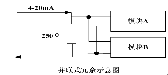
Figure 4-1-3 Schematic diagram of parallel redundancy of I/O modules
The switching redundancy mechanism represented by Yokogawa CS3000 and Emerson DeltaV is based on the redundant built-in switch of the module. Only the main module switch is turned on, and the standby module switch is not turned on. The switched redundancy diagram is as follows:

Figure 4-1-4 Switching redundancy of the I/O module
Parallel redundancy and switched redundancy have their own advantages and disadvantages: the advantage of parallel redundancy is that there is no time to re-establish steady state after switching, and the response speed is fast. The disadvantage is that a sampling resistor is shared, and the danger is concentrated. Once the resistance is damaged, two None of the modules work. In addition, the sampling resistor is separated from the module, and the accuracy and stability control are difficult. The advantage of switched redundancy is that it is dangerously dispersed and there are no shared devices. Sampling is integrated inside the module with high precision and stability. The disadvantage is that the steady-state working environment needs to be re-established after switching, and the time is longer than the parallel type.
The fieldbus communication module mainly includes:
1) Serial Card serial communication module, mainly used for protocol communication such as Modbus.
2) Foundation FieldBus Card FF bus communication module.
3) ProfiBus DP/PA Card for DP/PA bus communication.
4) Wireless Communication Card for wireless instrument communication.
5) DeviceNet and AS-Interface, factory automation mainstream fieldbus.
After the fieldbus module needs to pass the compatibility test with the third-party bus device, the specific bus instrument can be selected, otherwise there will be communication incompatibility risk. Different from the traditional instrument, when the bus instrument is in use, the upgrade with the communication module will be difficult to avoid. Therefore, maintenance work requires a high level.
3.3 Software selection
1) Configuration management software
The configuration software is used to configure, deploy and manage the entire DCS system and to undertake the main configuration process in the configuration process. Offline configuration software includes engineering total control, graphic editing, control logic configuration software, report configuration software, etc., as well as the completion of project compilation, download, project management, project management and other functions. The configuration management software should conform to the control algorithm programming software of IEC61131-3, support CFC, SFC, LD, ST configuration language, and support user-defined various function blocks and scripting languages. Any configuration modification can be completed online, including the control algorithm, hardware configuration addition, deletion, modification, system database, graphic configuration, system configuration and other configuration content, can be done on-site without parking without disturbing And modification, greatly improving the maintainability and availability of the system. The configuration software should pay attention to the perfection of the control functions, such as alarm diagnosis, customization, self-tuning, optimization algorithms, complex algorithms, and industrial application packages.
2) Run the software online
The monitoring system is oriented to the operator, providing data to the user by simulating flowcharts, bar graphs, numerical tables, trend curves, reports, buttons, dialog boxes, etc., executing operational commands and transmitting them to the field control station. The monitoring system is oriented to the operator, providing data to the user by simulating flowcharts, bar graphs, numerical tables, trend curves, reports, buttons, dialog boxes, etc., executing operational commands and transmitting them to the field control station. Online permission software should pay attention to the supported system scale, man-machine interface optimization, alarm diagnosis perfection, operation quality, real-time command, screen response time, historical storage quantity and time.
Through the monitoring system, operators and engineers can complete: monitor the automatic control process, real-time manual intervention, automatic printing or print job reports and other required information, and also provide screens and data to the MIS network through factory-level monitoring. Manager. Real-time data acquisition, dynamic data display, process automatic control, sequence control, advanced control, alarm and log detection, monitoring, and operation can be completed, and data can be recorded, counted, displayed, printed, and the like.
3) Controller software
It is used to complete on-site signal acquisition, engineering unit transformation, control and interlock control algorithms, control output, and transfer of data and diagnostic results to the operator station via the system network.
4) Auxiliary software
It is used to complete some auxiliary configuration and system query and management functions of the DCS system, including: OPC communication software, historical offline query tool, system upgrade tool, software version management tool, system simulation software, and authorization management tool.
4 Historical changes and development trends of DCS systems
Since Honeywell and YOKOGAWA launched the DCS system in 1975, the DCS system has experienced nearly 40 years, and the process automation control system has undergone earth-shaking changes, and has been developing with the rapid development of information technology and IT technology; We must understand history and predict the future.
4.1 Before 1975
Before the introduction of the DCS system, the process industrial control still stayed at the stage of process instrument automation control, and experienced the development of pneumatic instruments and electric instruments. The whole process control automation level is very low, the maintenance and operation personnel are heavy and man-made. There are many mistakes; complex process control cannot be realized, let alone advanced or optimized algorithm control, low production efficiency, high energy consumption, high production cost and maintenance cost.
4.2 Between 1975 and 1985
This is the rapid development stage of DCS, showing the phenomenon of blooming. Since YOKOGAWA and Honeywell have successively launched the distributed control system DCS, they have achieved good application performance and application effects, realized the concept of distributed control, centralized operation and management, and various circuits and More coordinated operation between the devices, improved operational stability and safety, decentralized control, dangerous dispersion and isolation, easy to install and maintain equipment.
The development history of YOKOGAWA's DCS system is shown in Figure 4-1-5.
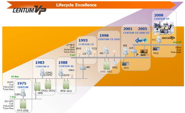
Figure 4-1-5 Development history of YOKOGAWA's DCS system
The main features of YOKOGAWA's CS3000 system are stable and reliable. The main performance is in large-scale chemical industry, and the application performance in power plants, metallurgy, building materials and other industries is relatively small. Relatively conservative in the application of information integration, it is not as radical as the European and American systems.
The main change of YOKOGAWA's CS3000 system in recent years is that the original large board is transposed into small modules, and the original dedicated V-NET network (coaxial cable) is cancelled and merged into the Ethernet on the network.
The development history of Honeywell's DCS system is shown in Figure 4-1-6.
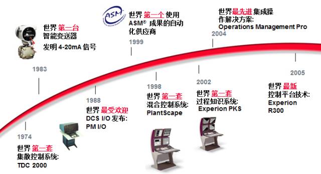
Figure 4-1-6 Development history of Honeywell's DCS system
The main feature of the Honeywell system is the integration of information technology, emphasizing the integration of the entire plant integration solution. Mainly used in petrochemical and chemical industries. Almost no power plants are involved.
The main change in Honeywell's PKS system was the replacement of hardware from a large board (PM) to a modular structure (C300), but experienced a less successful C200 hardware change. The C200 actually uses AB (Allen Bradley) hardware system integration.
Invensys introduced its I/A series DCS control system in 1987, and Invensys actually acquired the Foxboro I/A system. It is involved in both chemical and power plants, but the performance is not high. The development process is shown in Figure 4-1-7.
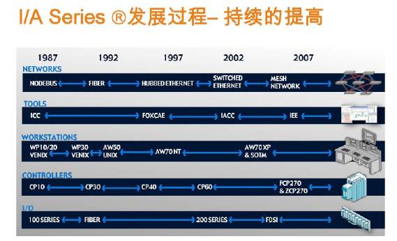
Figure 4-1-7 Invensys DCS Development History
Emerson has two systems, DeltaV for chemical and Ovation for power plants. It is a DCS manufacturer with two top performances in the industry.
ABB's AC800 system holds a high position in building materials, papermaking and metallurgy. Another set of NF90 systems that acquired the original Bailey was mainly used in power plants, and was gradually retired due to the long time.
The most influential DCS manufacturers in China are Helix, Zhejiang Zhongkong, Guodian Zhishen, and Nanjing Keyuan. The main performance of Zhejiang Zhongkong is in petrochemical and chemical industry, and the power plant is hardly involved. Guodian Zhishen is mainly used in large power plants in the Guodian system. Nanjing Keyuan's main performance is in small thermal power. The domestic Hollysys is the only DCS supplier to lead in both chemical and power plants. It is also the only DCS manufacturer in the US NASDAQ. Fortunately, among the domestic DCS companies, Hollysys and Zhejiang Zhongkong already have the same price competition with foreign DCS companies. Three years ago, foreign companies were allowed to win 10-20% higher than domestic companies. Now foreign companies Quotes are even lower than domestic companies. For example, in the bidding of power plants, although Emerson's Ovation reputation is the best, but the fieldbus technology is not leading, Siemens fieldbus technology is very strong, but the reputation of the DCS system in the power plant is not dominant, and the Hollysys system has a good reputation for power plant application. And the powerful fieldbus technology capabilities, but the comprehensive strength exceeds the two.
Hollysys took the lead in launching the first domestic DCS system HS1000 in 1993, and the development history of Lishi DCS is shown in Figure 4-1-8.
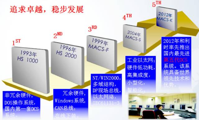
Figure 4-1-8 Development history of Lishi DCS
After 20 years, in the absorption of the advantages of excellent DCS at home and abroad, combined with 20 years of experience in the field, launched a new generation of MACS-K series DCS system in early 2012, as shown in Figure 4-1-9, representing DCS New trends in development.
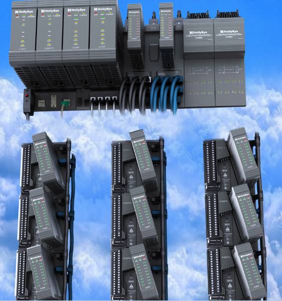
Figure 4-1-9 and the new generation of MACS-K series DCS system
The MACS-K series has the following features:
·Highly reliable design concept
The safety system design concept is adopted, such as the signal to increase the quality level judgment, the fault-oriented safety, and improve the system reliability. Safety measures in unexpected situations are the focus of reliability design.
·Multiple isolation technology
The system bus and the module are optically isolated; the system power supply and the field power supply are used to isolate the power supply; the channels of the module are electrically isolated; the network has a physical layer and a protocol layer double isolation. The principle of failure non-proliferation is the goal of isolation technology.
·Adapt to harsh environment
The system is designed based on harsh industrial environment and conforms to EMC design specifications. The anti-interference is in line with the international standard IEC61000 under industrial environment. The system anti-corrosion capability meets the requirements of ISA S71.04 standard G3.
·Network full technology
The system network adopts deterministic real-time Ethernet communication protocol, which is equipped with a switch with firewall to ensure network security. The controller CPU adopts PowerPC architecture industrial-grade chip, based on real-time operating system, built-in anti-network storm component; multi-bit representation And the signal quality is judged, and the fault is reversed to safety.
·Comprehensive diagnostic technology
The field control station and I/O modules are equipped with intelligent diagnostic units, each unit can complete self-diagnosis. All types of faults, such as communication, disconnection, short circuit, over-range, can be detected and reported to the operation in time. Station.
·Fail safe technology
Signal quality verification is performed before the logic calculation, and the output can be automatically switched to a preset safety value when the fault occurs. Uses multiple bit bits to represent 0/1 for fault tolerance and supports ECC memory error detection. The entire system follows the safety design philosophy.
· Fully redundant design concept
The various components of the system, including the historical station, system network, control network, controller, power module, and I/O modules, can be redundantly configured.
·Electromagnetic Compatibility
The system is designed based on harsh industrial environment, anti-electromagnetic interference is in line with IEC61000, and all modules have passed CE certification.
·Advanced system architecture
The system supports three kinds of system network structures: P-TO-P (Peer-to-Peer Network), C/S (Client/Server), P-TO-P and C/S (Hybrid). Industrial Ethernet connections that support star, ring or bus topologies.
·Fieldbus technology
Compatible with various fieldbuses, supporting various protocols such as HART, PROFIBUS-DP, PROFIBUS-PA, MODBUS.
·Human engineering technology
The system software function and the HMI human-machine interface fully adopt the human factor engineering analysis technology, so that the software is easy to use, easy to use, and even the technical personnel of the industry can learn directly from the learning; the software design fully considers to avoid the occurrence of human error. The system design considers the user's convenience, easy maintenance, easy replacement, and provides complete system status and diagnostic information. All hardware modules are equipped with hardware hot-swap, online download and online electronic maintenance manuals, providing customers with convenient and safe on-site maintenance without any process that leads to non-stop or interfere with production.
·Compliance with international standards
The control algorithm programming software conforms to IEC61131-3, supports CFC, SFC, LD, ST configuration language, and supports user-defined various function blocks and scripting languages.
· Comprehensive online configuration function
Any configuration modification of the MACS-K system can be completed online, including the addition of control algorithms, hardware configuration, deletion, modification, system database, graphic configuration, system configuration and other configuration contents. Uninterrupted installation and modification of parking greatly improve the maintainability and availability of the system.
· Support for large system applications
The MACS-K system supports multi-domain architecture, supports up to 15 domains, and supports up to 983,025 database points. The MACS-K system supports multiple engineer station collaborative configuration functions, which ensures that multiple people work together at the same time in the implementation of very large projects.
· Protect users from existing investments
The MACS-K system is compatible with the FM and SM series I/O modules that work in time and facilitates the upgrade of the old system, and can be mixed with the old version software of Hollysys to protect the investment cost of the old users.
· Provides a total solution
The MACS-K system can be used with other products of Hollysys, including: AMS (asset management system), control algorithm programming software conforming to international standards in accordance with IEC61131-3, supporting CFC, SFC, LD, ST configuration language, supporting users. Define various function blocks and scripting languages.
· Comprehensive online configuration function
Any configuration modification of the MACS-K system can be completed online, including the addition of control algorithms, hardware configuration, deletion, modification, system database, graphic configuration, system configuration and other configuration contents. Uninterrupted installation and modification of parking greatly improve the maintainability and availability of the system.
· Support for large system applications
The MACS-K system supports multi-domain architecture, supports up to 15 domains, and supports up to 983,025 database points. The MACS-K system supports multiple engineer station collaborative configuration functions, which ensures that multiple people work together at the same time in the implementation of very large projects.
· Protect users from existing investments
The MACS-K system is compatible with the FM and SM series I/O modules that work in time and facilitates the upgrade of the old system, and can be mixed with the old version software of Hollysys to protect the investment cost of the old users.
· Provides a total solution
The MACS-K system can be combined with other products from Hollysys, including: AMS (Asset Management System), BATCH (Batch Control), APC (Advanced Process Control), SIS (Safety Instrumentation System), MES (Production Execution System), OTS (Operator Simulation Training System) Seamless integration to provide users with a total solution.
In 2012, the first set of safety instrumented systems independently developed by Hollysys Group and having independent intellectual property rights in China, passed the SLI3 certification of Rheinland Industrie Service GmbH, which marks the long-term monopoly of foreign countries. The instrument system) was broken by the time. The Hollysys SIS system uses a three-and-two-band diagnostic framework (3OO2D), as shown in Figure 4-1-10.
Figure 4-1-10 and the SIS system
Affected by the development of information technology (network communication technology, computer hardware technology, embedded system technology, fieldbus technology, various configuration software technologies, database technologies, etc.), as well as the user's demand for advanced control functions and management functions, Each DCS manufacturer (represented by Honeywell, Emerson, Foxboro, Yokogawa, ABB, and domestically represented by Hollysys and Zhejiang Zhongkong) has upgraded the technical level of the DCS system and continuously enriched its content. The architecture of DCS is mainly divided into four layers: the field instrument layer, the control unit layer, the factory (workshop) layer and the corporate management. Generally, DCS vendors mainly provide Layer 3 functions in addition to enterprise management, while enterprise management connects to third-party management software platforms (ERP, CRM, SCM, etc.) by providing an open database interface. Therefore, DCS today provides all the control and management functions at the factory (workshop) level and integrates the information management functions of the enterprise. Information and integration basically describe the changes that are taking place in today's DCS systems. Users can already collect information data from the entire factory floor and process, but users want this large amount of data to be reflected in a suitable way and help the decision-making process, allowing users to get the data they need in a convenient way, in a convenient way. Informatization is reflected in the fact that each DCS system is not a control system based on control functions, but a comprehensive platform system that fully utilizes information management functions. DCS provides the entire information channel from the field to the equipment, from the equipment to the workshop, from the workshop to the factory, from the factory to the corporate group. This information fully reflects the comprehensiveness, accuracy, real-time, system and security.
As the Iranian nuclear power plant was attacked by the Stuxnet virus, a virus was created specifically for the industrial control system. Therefore, the security of industrial systems has become an unprecedented new requirement for the development of DCS, emphasizing the entire layered security solution from network security, system security, module security, equipment security, and top-down. Corresponding development with border firewall (for connection with third-party systems), distributed firewall (for controller and operator station), with network storm suppression and packet filter switch, with built-in anti-network storm component controller, based on white The list handles the operator station and other equipment such as anti-virus software.
With the increasing application of fieldbus technology, the combination of traditional I/O acquisition technology and fieldbus will be the general trend of DCS applications. Traditional I/O acquisition technology is stable, reliable, easy to use, and has good real-time performance, but the amount of information and diagnostic functions are limited. The fieldbus technology has the characteristics of large amount of information, complete diagnosis and convenient wiring, and is suitable for connecting large-scale multi-functional intelligent devices with DCS. Therefore, foreign honeywell, Emerson, ABB, Siemens, domestic and Lishi, Zhejiang Zhongkong have developed better in fieldbus applications. In comparison, other domestic companies are just getting started.
With the refinement requirements of different industries, users hope that DCS suppliers will not only provide only one set of equipment, but also provide a complete set of industrialized overall solutions, launch the industry custom package function, commit to energy saving and emission reduction in the industry, and improve product quality. And production efficiency. After-sales service: Traditional on-site services are degrading, and remote cloud service platforms that support remote access, remote diagnostic data extraction and remote optimization and adjustment are emerging in large DCS manufacturers.
P3.91-7.82 Transparent LED Display
Features:
*Ventilated light
*Free air conditioning heat saving energy
*Environmental protection- it uses only a third of the power of a conventional Led screen
* Convenient installation High compatibility
* Nova MSD 300 sending card and Nova A5S receiving card
* High debugging brightness and no damage to gray scale, achieving the debugging technology for nice image.
* Passed the TÃœV,FCC,ROHS,CE cetification.
Our company have 13 years experience of led display and Stage Lights , our company mainly produce Indoor Rental LED Display, Outdoor Rental LED Display, Transparent LED Display,Indoor Fixed Indoor LED Display, Outdoor Fixed LED Display, Poster LED Display , Dance LED Display ... In additional, we also produce stage lights, such as beam lights Series, moving head lights Series, LED Par Light Series and son on...
Application:
* Business Organizations:Supermarket, large-scale shopping malls, star-rated hotels, travel agencies
* Financial Organizations:
Banks, insurance companies, post offices, hospital, schools
* Public Places:
Subway, airports, stations, parks, exhibition halls, stadiums, museums, commercial buildings, meeting rooms
* Entertainments:
Movie theaters, clubs, stages.
Transparent LED Display,Transparent Led Display,Transparent Poster Led Display,Led Screen Panel
Guangzhou Chengwen Photoelectric Technology co.,ltd , https://www.cwledpanel.com