1. What is the baud rate?
No matter what kind of microcontroller, when using serial communication, there is a very important parameter: baud rate. What is the baud rate: The baud rate is the number of bytes transmitted per second. In the process of transmitting data, the baud rate is the same, which is the basic guarantee for successful communication. Let's take the STM32 microcontroller as an example to explain the calculation method of the serial port baud rate.
2. STM32 baud rate related registers
The STM32 MCU sets only one register for the baud rate: USART_BRR register, as shown in the figure below.
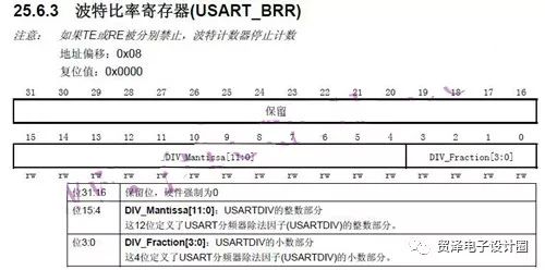
The valid number of bits in this register is 16 bits. The first 4 bits are used to store the fractional part and the last 12 bits are used to store the integer part. After calculating the baud rate, the value can be filled in the baud rate. Here's how to calculate.
3. Baud rate calculation method
The STM32 data sheet gives the calculation method and has a formula as shown below:

In this formula, there are three variables, two of which we know, Fck and Tx/Rx baud rates are known, and USARTDIV is unknown. It can be seen from the description of the formula that if USART1 is used, then Fck is PCLK2=72MHz, otherwise PCLK1=36MHz, and the Tx/Rx baud rate parameter is known. Simply calculate the value of USARTDIV and assign it to the USART_BRR register. Taking 115200 as an example, the formula is deformed to obtain: USARTDIV = 72 × 1000000 / (16 × 115200) = 39.0625. Write 39.0625 to USART_BRR.
As mentioned earlier, the first 4 bits of USART_BRR store the fractional part, and the last 12 bits store the integer part.
The fractional part DIV_Fraction = 0.0625 × 16 = 1 = 0x01; that integer part DIV_Mantissa = 39 = 0x27; then USART_BRR = 0X271;
The data sheet gives us a data sheet:
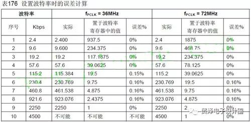
On this data sheet, the commonly used baud rate values ​​have been calculated and can be used directly. But if we want to make the calculation of the baud rate into a way of passing parameters, such as: USART_INIT(uint_t 16 Baud), we only need to write USART_INIT (9600), USART_INIT (115200) when calling, then how to write the program? ?
4. Program implementation
The following is a register version of the program.

The first step of the program is 45 lines: first calculate USART_DIV, this is the deformation of the previous formula; the second step of the program is 46 lines: obtain the integer part of USART_DIV; the third step of the program is 47 lines: obtain the fractional part of USART_DIV; the fourth step of the procedure is 48 Line: Shift the integer part to the left by 4 bits, that is, the last 12 bits of the BRR register; the fifth step of the program is 49 lines: the integer and the fractional part are combined, that is, the first 4 bits and the last 12 bits are recombined; Step 50: Assign the calculated value to the BRR register.
Such a function that takes the baud rate as a formal parameter is completed. From the above point of view, the calculation of the baud rate does not seem to be very difficult.
Antenk DVI Series Digital Video Interface connectors are the standard digital interface for flat panels, video graphics cards, monitors and HDTV units. This series includes DVI-D (Digital), DVI-A (Analog) and DVI-I (Integrated Digital/Audio). Their unique crossing ground blades provide high speed performance at low cost. They are available in Straight or Right Angle PCB mount receptacles and mating male cable connectors. They support a data transfer rate of 4.95Gbps with a dielectric withstanding voltage of 500VAC. Each version features our specially designed contacts which improve signal performance and a zinc alloy shield that reduces electromagnetic interference (EMI).
Digital Visual Interface Cable Connectors
DVI ConnectorWith the advent of technologies such as DVD players, high-definition televisions, and even digital cable, the need for more advanced cables and connectors has increased. Digital Visual Interface (DVI) is one response to the growing need for interconnected systems, enabling digital systems to be connected to an array of displays. Yet DVI cables and connectors can also be complicated, and may lead to confusion between High Definition Multimedia Interface (HDMI) and DVI. Although the two systems have much in common, they service different niches of digital technology.
Digital Visual Interface
Older systems aren`t necessarily outdated systems. Although DVI preceded HDMI, it`s still widely used in both business and domestic settings. DVI connectors are designed to handle digital data transmission, incorporating three transmission channels in every connector link. The maximum bandwidth for data transfer is 165 megahertz, which is enough to relay up to 165 million pixels per second. Data is encoded for effective transfer, but a single link can handle around 4.95 gigabits per second of information. Double links can handle twice that amount.
Because a DVI cable carries information over a 165 megahertz bandwidth, complete digital resolution can be obtained. Using double link connectors increases the speed of transmission, but requires another cable. However, not many devices depend solely on a double link DVI, so this technolgy can be used on an as-desired basis.
Types of DVI Connectors
There are three general categories of DVI cable connectors: DVI-Digital (DVI-D), DVI-Integrated (DVI-I), and DVI-Analog (DVI-A). However, most connectors fall into one of the first two groups.
A standard DVI Connector is 37 mm wide and has 24 pins, 12 of which are used for a single link connection. When analog is involved, four additional pins are needed to support the additional lines of an analog signal. It is not possible to cross from a digital source to an analog display or vice versa. In those instances, an integrated connector is probably the best option. There are five common types of DVI connectors.
DVI-I Single Link
This kind of connector has three rows, each with six pins. There are two contacts. Because the connector is integrated, it can be used with both analog and digital applications.
DVI-I Dual Link
A DVI-I dual link connector can also be used with both digital and analog applications, but is configured with more pins to accommodate a dual connection. There are three rows with eight pins each, as well as two contacts.
DVI-D Single Link
Specifically designed for digital applications, a DVI-D single link connector has three rows of six pins, and looks much like a DVI-I single link connector. However, a DVI-D connector has no contacts.
DVI-D Dual Link
Also made specifically for digital applications, a DVI-D dual link features more pins (three rows of eight) for dual connections. Like a DVI-D single link, a DVI-D dual link connector has no contacts.
DVI-A
This particular type of connector can only be used for analog applications, and has three rows of pins. One row has five pins, one has four pins, and the last row has three pins. Like single link connectors, a DVI-A link connector has two contacts.
Male DVI Connector
ShenZhen Antenk Electronics Co,Ltd , https://www.antenkcon.com