The cost of the nRF24L01 is low, but the internal communication needs to be SPI communication, which is slightly complicated. At the same time, the RF is too dedicated, and it needs to be converted when accessing other systems, which is inconvenient.
ESP8266 is a cheap but almost versatile WIFI chip introduced by Lexin. It is widely used by various intelligent hardware. According to its datasheet, it not only supports SPI, but also communicates through I2C, UART, etc., especially UART, which directly supports AT. The instructions greatly simplify the development and are quite convenient. This article uses the AT mode.
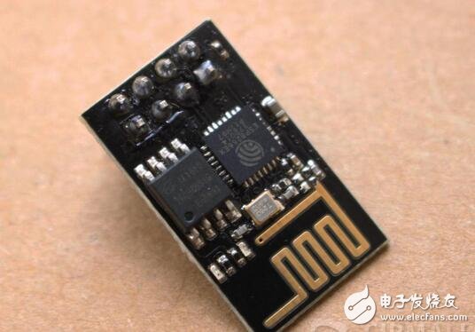
ESP8266 development board, about 12 TB, ESP8266 on the right, 25Q80BVSIG on the left, 1M flash memory.
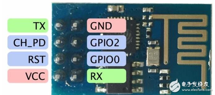
TX: serial port write
GND: Ground
CH_PD: High level is available, low level is off
GPIO2: Can be left floating
RST: reset, can be left floating
GPIO0: Pull-up is in working mode, pull-down is in download mode, can be left floating
VCC: 3.3V (cannot be connected to 5V, burning)
RX: Serial port read
2, wiring instructions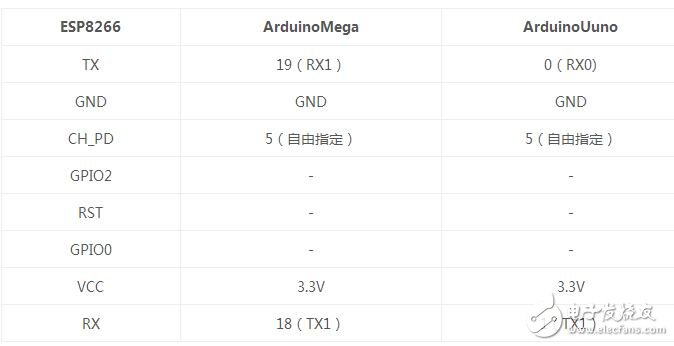
The default baud rate of the ESP8266 serial port is 115200, mega can also be directly connected to RX0/TX0. For the convenience of debugging, RX0/TX0 in this article is left as the debugging window, and RX1/TX1 interacts with the chip. If it is UNO, if you want to see debugging information, you can only add a soft serial port.
Third, the code & runDirectly read and write AT commands directly through the serial port, but the instructions are more and the processing is cumbersome.
Find the following library to encapsulate the AT command, very convenient to use, recommended.
The Git address is:
https://github.com/ekstrand/ESP8266wifi.git
The specific AT command and ESP8266 related documents can be found on the official website of Lexin:
Http://espressif.com/zh-hans/support/download/documents
1) ESP8266 library installation
After downloading the ESP8266 library above, copy it to the libraries directory under the Arduino installation directory. After starting the ArduinoIDE, select ESP8266_tcp_cli from the example.
The library supports 3 client connections and 1 listener connection by default. To increase the number of macros in the header file you need to modify:
1 define SERVER '4'
2 define MAX_CONNECTIONS 312
2) Code modification
The library design is very flexible, set up 3 serial ports, into the serial port, out the serial port and debug serial port.
The serial port and the output port are used for AT command transmission and reception, and are connected to the serial port of ESP8266. The debug serial port can display the specific interaction (AT command information, etc.). The original example uses UNO because it has only one hard serial port, so it is changed. Applicable to Mega to view debug information.
3) running
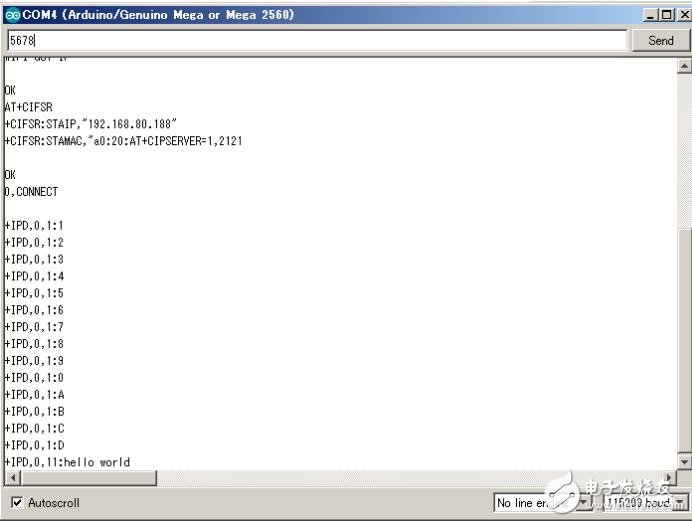
After loading and running, if the WIFI settings are normal, you can access WIFI and obtain IP, as follows:
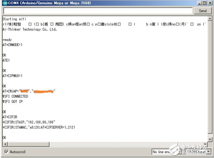
You can see the AT command output from the debug serial port, which is connected to WIFI and obtain the IP of 192.168.80.188.
In addition, port 2121 is also monitored successfully.
You can use telnet to simulate the client. After the connection is successfully established, enter data 0~D, hello world.
The entered data can be seen in the COM monitor from the corresponding AT command. As shown below:
Removed the processing related to the soft serial port from the original example, as follows
#include 《ESP8266wifi.h》
#define esp8266_reset_pin 5
#define SERVER_PORT "2121"
#define SSID “XXXXâ€
#define PASSWORD “yourpassâ€
// Initialize, serial port 1 and ESP8266 interact, serial port 0 does debug output, pin5 does reset
ESP8266wifi wifi (Serial1, Serial1, esp8266_reset_pin, Serial);
Void processCommand(WifiMessage msg);
Uint8_t wifi_started = false;
// Custom application layer commands, which can be modified according to their own application
Const char RST[] PROGMEM = "RST";
Const char IDN[] PROGMEM = "*IDN?";
Void setup() {
// Debug serial port startup, baud rate can be specified at will
Serial.begin(115200);
// ESP8266 default baud rate is 115200 (can be modified by AT command)
Serial1.begin(115200);
While (!Serial) // Wait for the serial port to initialize successfully
;
Serial1.println("StarTIng wifi"); // command
Serial.println("StarTIng wifi"); // Debug log output
wifi.setTransportToTCP(); // TCP mode (default setting)
wifi.endSendWithNewline(false); // Send data automatically ends (default setting)
Wifi_started = wifi.begin(); // WIFI boot
If (wifi_started) { // If WIFI is successfully initialized
wifi.connectToAP(SSID, PASSWORD); // Specify username and password to connect to WIFI
wifi.startLocalServer(SERVER_PORT); // This machine (Arduino) listens on port 2121 (doing server)
} else {
// ESP8266 isn't working.
Serial.println("ESP8266 isn't working..");
}
}
Void loop() {
staTIc WifiConnection *connections;
// check connections if the ESP8266 is there
If (wifi_started)
wifi.checkConnections(&connections); // check/get the status of all current connections
// check for messages if there is a connection
For (int i = 0; i " MAX_CONNECTIONS; i++) { // The default maximum is 3
If (connections[i].connected) {
// See if there is a message
WifiMessage msg = wifi.getIncomingMessage();
If (msg.hasData) { // if there is data
processCommand(msg);
}
}
}
}
Void processCommand(WifiMessage msg) { // data processing function
Char espBuf[MSG_BUFFER_MAX];
Int set;
Char str[16];
Serial.print(msg.message);
// The following is the application level processing
Sscanf(msg.message, "%15s %d", str, &set);
Serial.print(str);
Serial.println(set);
If ( !strcmp_P(str, IDN) ) {
Wifi.send(msg.channel, "ESP8266wifi Example");
}
// Reset system by temp enable watchdog
Else if ( !strcmp_P(str, RST) ) {
Wifi.send(msg.channel, "SYSTEM RESET..");
// soft reset by reseting PC
Asm volatile (" jmp 0");
}
// Unknown command
Else {
Wifi.send(msg.channel, "ERR");
}
}
A motor with gearbox is a mechanical device utilized to increase the output torque or change the speed (RPM) of a motor. The motor's shaft is attached to one end of the gearbox and through the internal configuration of gears of a gearbox, provides a given output torque and speed determined by the gear ratio.
motor with gearbox,motor and gearbox,24v dc motor with gearbox,1hp motor with gearbox,12v electric motor with gearbox,small electric motors with gearbox
Shenzhen Maintex Intelligent Control Co., Ltd. , https://www.maintexmotor.com