The main functions of the home intelligent control system are focused on home security alarms, telephone or computer remote control, infrared remote control, automatic meter reading control, lighting and humidity control. According to the different data transmission and function of the intelligent terminal device, it can be divided into two types of subnets, one is the home automation control device that transmits data with small data volume and low rate; the other is the transmission of multimedia information, (video, audio signal) ), large signal volume, fast rate, such as video conferencing, audio on demand and so on. The home intelligent terminal device can use the bus structure group to build the wired subnet and the wireless subnet. Since the devices are distributed in different places in the home, it is more complicated to set up the wired subnet wiring, but if the plc and the CAN bus are used to construct the network, cut costs.
CAN (Controller Area Network) is a serial data communication protocol developed by Bosch in Germany in the early 1980s for vehicle detection and control. It is a multi-host bus, and the communication medium can be twisted pair. Shaft cable or fiber optic cable with a communication rate of 1 Mb/s. The CAN bus has excellent performance, high reliability and unique design, and is widely used in industrial automation, transportation, medical equipment, and construction, environmental control and many other departments.
1 The composition of the home intelligent control system
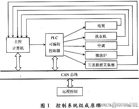
The home intelligent control system is the core of the command communication and information management of TV, washing machine, air conditioner and water meter, electric meter, gas meter and other equipment. The main function is to carry on the digital communication with the remote control system, receive various control passwords, and complete the corresponding Real-time control of the device.
Any unit with an embedded microprocessor or microcomputer in the control system is connected to each other through a CAN bus. Form a distributed local network to achieve data exchange and information resource sharing. This design has the following advantages: reduced communication port and connection cable; strong anti-interference ability; flexible configuration, convenient system expansion and upgrade; simple debugging and convenient maintenance.
The principle of the home intelligent control system composed of CAN bus is shown in Figure 1.
2. PLC and CAN bus connection
Taking GEFANUC series 90PLC as an example, a connection scheme between PLC and CAN bus is given.
The GE Series 90 PLCs have a converted RS232 serial communication port through which the programming computer communicates and programs with the PLC. The RS232 standard level uses negative logic, which stipulates that any level between +3 and +15V is a logic "0" level, and any level between -3 and -15V is a logic "1" level. The CAN signal is transmitted using differential voltage. The two signal lines are called "CAN_H" and "CAM_L". The static state is about 2.5V. The state at this time is represented as logic "1", which can also be called "recessive". ; Use CAN_H to be higher than CAN_L to indicate a logical "0", called "dominant". In the case of dominant, the usual voltage values ​​are: CAN_H = 3.5V, CAN_L = 1.5V.
The frame format of the RS232 serial port is: 1-bit start bit, 8-bit data bit, 1-bit programmable 9th bit (this bit is the address/data bit for transmission and reception), 1 stop bit. The CAN data frame format is: frame information + ID + data (can be divided into standard frame and extended frame format). Therefore, a microcontroller is required to realize the conversion of level and frame format, etc., and its conversion mode is shown in Figure 2.
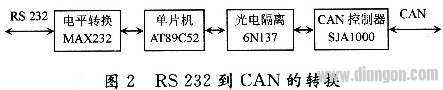
Using the single chip AT89C52 as the microprocessor; using SJAl000 as the CAN microcontroller, SJAl000 integrates the physical layer and data link layer functions of the CAN protocol, which can passively process the frame processing of communication data; high-speed optical isolation is realized by 6N137, Its role is to prevent serial interference; MAX232 is used to complete the conversion of RS232 level to the TTL level of the microcontroller interface chip. See the SJAl000 data for the specific hardware interface circuit, but there are the following points to note:
(1) A 120Ω resistor is connected to both ends of the CAN bus. Its function is to match the bus impedance and improve the anti-interference and reliability of data communication. However, in practice, it is only necessary to ensure that the jumper resistance between "CAN_H" and "CAN_L" in the CAN network is 60Ω.
(2) SJAl000's 20-pin RXl can be grounded when not in use, with CDR. The setting of 6 can greatly increase the bus length.
(3) The connection of pins TX0 and TX1 determines the level of the serial output. For the specific relationship, refer to the setting of the output control register OCR.
(4) The RS pin of the AT82C250 has a slope resistor indirectly with the ground. The size of the resistor can be adjusted according to the bus communication speed, generally between 16 and 140 kΩ.
(5) The external capacitors of MAX232 need 4 electrolytic capacitors C1, C2, C3, C4. These capacitors are also required for internal power conversion. The values ​​are all 1μF/25V. The tantalum capacitor should be used and the position application amount is close to the chip. The power supply Vcc Connect a 0.1μF decoupling capacitor between ground and ground.
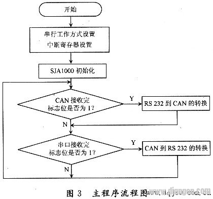
Under the micro-processing control, when RS232 and CAN exchange data, the serial port receiving and CAN interrupt mode can improve the working efficiency. The initialization of SJAl000 can only be performed in the reset mode, including the setting of the working mode, the setting of the clock division and acceptance filter registers, the setting of the baud rate parameter, and the setting of the interrupt enable register. The main program flow chart is shown in Figure 3.
Whether the data can be accurately transmitted depends on the baud rate and flow control, which is also a place that cannot be ignored in software design. Therefore, the following mainly introduces the setting of CAN baud rate, automatic detection of serial port baud rate, and serial data flow control.
One of the elements in the CAN protocol is the baud rate. The bit sampling point position and sampling times in the bit period can be set so that the application network performance can be freely optimized, but in the optimization process, attention should be paid to the tolerance of the bit timing parameter reference reference oscillator and the different signal propagation delays in the system. Relationship between.
The bit rate fbit of the system represents the amount of data bits transmitted per unit time, ie the baud rate fbit = 1/tbit. The nominal bit timing consists of three non-overlapping segments SYNC_SEG, TSEG1 and TSEG2, which are tSYNC_SEG, tTSEG1 and tTSEG2, respectively. Therefore, the amount of positioning period tbit is the sum of 3 time periods: tbit = tSYNC_SEG + tTSEGl + tTSEG2. These segments in the bit period are represented by an integer number of basic time units. The time unit is called time share TQ, and the duration of the time share is one cycle tSCL of the CAN system clock, which can be obtained from the oscillator clock cycle tCLK. The CAN system clock can be adjusted by programming the prescaler factor (Baud Rate Preset BRP), ie tSCL = BRP × 2tCLK = 2BPR / CLK.
Another important time period for CAN bit timing calculation is the sync jump width (SJW), which is tSJW. The SJW segment is not a segment of the bit period, but defines the maximum number of TQs for the bit period that is grown or shortened during the resynchronization event. In addition, the CAN protocol allows the user to specify the bit sampling mode (SAM), which is a single sample and a three sample mode (one out of three samples). In single sampling mode, the sample point is at the end of the TESG1 segment. The three-sampling mode takes two more sampling points than the single-sampling, and they are one TQ apart in front of the end of the TSEG1 segment. The above mentioned BPR, SJW, SAM, TESG1, TESG2 can be defined by the user through the built-in registers BTR0 and BTR1 of the CAN controller. After setting BTR0 and BTRl, the actual transmission baud rate range is: maximum = 1 / (tbit - tSJW), minimum = 1 / (tbit + tSJW).
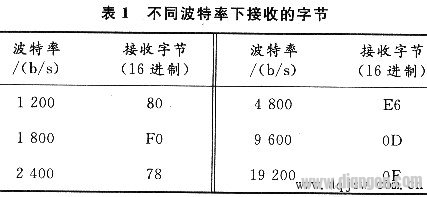
To detect the serial port baud rate of the conversion device, first set the receiving baud rate of the host (for example, 9600 b/s), and send a specific character in the terminal (taking the carriage return as an example), so that the host Based on the received character information, the communication baud rate of the conversion device can be determined. The ASCII value of the carriage return is 0DH, and the values ​​received at different baud rates are listed in Table 1.
When data is transferred between two serial ports, data loss often occurs. Since the MCU buffer is limited, if the buffer is full when receiving data, the data that continues to be sent at this time will be lost. The flow control can effectively solve the problem. When the data processing at the receiving end is not over, the flow control system will send a signal of "no longer receiving", and the transmitting end stops transmitting until the signal "can continue to be transmitted" is received. Send the data again. Therefore, flow control can control the progress of data transmission and prevent data loss. The two commonly used flow control are hardware flow control (including RTS/CTS, DTR/CTS, etc.) and software flow control XON/XOFF (continue/stop). The hardware flow control RTS/CTS is described below.
When using hardware for flow control, the serial terminal RTS and CTS are connected to the I/O port of the MCU, and the I/O port is set to 1 or 0 to receive and send the start and stop signals. A data terminal device (such as a computer) uses RTS to initiate the flow of data from the microcontroller, while a microcontroller uses CTS to initiate and halt the flow of data from the computer. When implementing this hardware handshake mode, a high-order flag and a low-level flag are set according to the size of the buffer of the receiving end during programming. When the amount of data in the buffer reaches a high level, the CTS line is set low at the receiving end (send logic 0) When the program at the transmitting end detects that CTS is low, it stops transmitting data until the amount of data in the buffer of the receiving end is lower than the low level and CTS is set high. RTS is used to indicate whether the receiving device is ready to receive data.
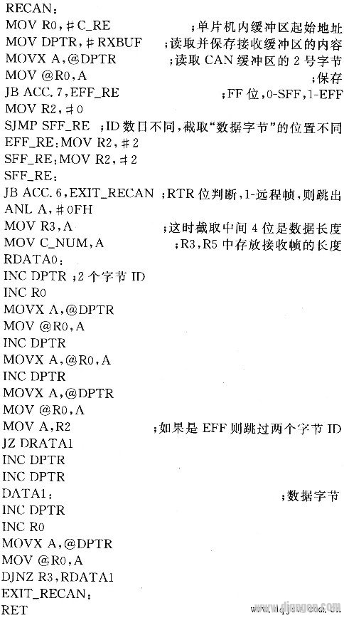
The following is the CAN Receive subroutine:
3. Conclusion
Through the analysis of the home intelligent control system, PLC and CAN bus are used to construct a control local area network. Through the test of the simulation system, the bus can completely control the home intelligent terminal equipment, but the stability and real-time of its control should be controlled. Further improvement is needed, and further research is needed on this basis.
Oil Filter For HONDA
HONDA Oil Filter Replacement,Oil Filter For HONDA Cars,HONDA Car Oil Filter,HONDA Auto Oil Filter
Zhoushan Shenying Filter Manufacture Co., Ltd. , https://www.renkenfilter.com