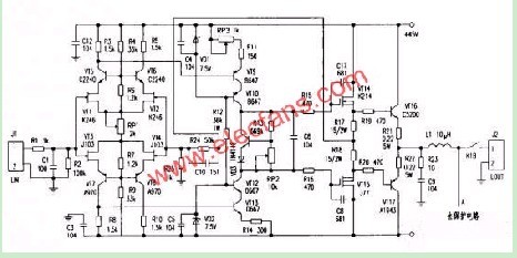
The figure above shows the left channel amplifier circuit of the power amplifier. R1 and C1 form a low-pass filter to filter out high-frequency interference signals mixed in the audio signal, and R2 is an input matching resistor. The audio signal from the source or the front stage is entered into the dual differential input circuit consisting of four FETs of VT1-VT4. The FET is a voltage control device with high input impedance and good frequency response. It is commonly found in some enthusiast-grade circuits. At the same time, its drain-source withstand voltage is low, and the power supply needs some special treatment. R4, R6, RP1, R7 and R9 form a DC voltage clamping circuit to power four input stage FETs. After calculating VT5, VT6 and VT7, VT8 base potential is ± 45V × (R6 + RP1 × 1/2) / (R4 + R6 + RP1 × 1/2) = ± 12.7V. Four FET drains The actual supply voltage is 12.7V-0.6V=12.1 V, which ensures that the FET operates in a low voltage state. VT1 and VT5 (other VT2 and VT6, VT3 and VT7, VT4 and VT8) form a common source common-base circuit (commonly known as Walman circuit). This circuit configuration has unparalleled advantages of other lines - frequency response, distortion Low, high gain, and good linearity. RP1 regulates the four input stage junction FET gate-source bias voltages, which in turn changes the input stage operating current. This circuit sets the input stage current to 1.6mA, so that the DC voltage drop on R3, R5, R8, R10 is 1.5kΩ×1.6mA=2.4V.
VT9, VT10 and VT12, VT13 are connected to a cascode-common base configuration to form a voltage amplification stage. The VD1, R12 and VD2 branches are common base pipe VT10, and the VT12 base provides a constant operating voltage. C4, CS is connected to VD1, and VD2 eliminates noise interference caused by Zener diodes. The 2.4V DC voltage drop on R3 and R8 is used as the base bias voltage of VT9 and VT13. The voltage amplification stage operating current is clamped at (2.4V-0.6V) /300Ω=6mA. The audio signal is VT9, VT13 After amplification, its collector enters the common-base circuit composed of VT10 and VT12, and is output from the collectors of the two tubes, and is fed to the push-level circuit composed of VT14 and VT15 via R15 and R16. RP3 regulates the DC potential of the symmetrical midpoint output of the output stage. The potential of this point is controlled within ±5 mV. VT11, VD3, R13 and RP2 constitute the push stage and power output stage bias circuit. Adjusting RP2 can change the gate potential difference between the two stages of push stage K214/J77, and then change the output stage VT16, VT17 by the voltage difference on R17, R18. Static bias state.
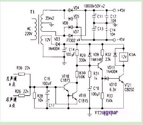
The figure below is the power supply and protection circuit of the machine. The protection circuit has the power-on delay and the mid-point DC overvoltage protection function of the main amplifier circuit output. When the power is turned on, the protection circuit supply voltage is charged to the C18 through the R29 and R31 branches. At the beginning, the VT20 base potential is low and cannot be turned on, resulting in the VD10 and VT21 being cut off, the relay K1 cannot be closed, and the normally open contact is disconnected from the power stage and the speaker. The connection avoids the impact of the starting surge current on the speaker. As the C18 charging voltage increases, the VT20 is saturated and the VD10 and VT21 are also saturated and turned on. The relay K1 is pulled in and the speaker is normally played. R29, R31 and C18 determine the length of the power-on delay.

Capacitor Motor,Furnace Capacitor,Start Capacitor,Capacitor Start Motor
Wentelon Micro-Motor Co.,Ltd. , https://www.wentelon.com