Brief description
In a switching system, in the case of a short circuit or an open circuit, the relay is often overloaded due to the presence of additional current or voltage. All relays have a maximum load current and thermal switching power. If this range is exceeded, the risk of the relay being soldered together increases, causing it to be unreleasable or the release time is too long.
The reason is that there is a capacitive device in this part of the power supply, which may release a large current, which generates heat so that the connection part melts and may be connected after cooling.
Adding additional current limiters can reduce this problem, but it is clear that adding a current limiter to the power section is also incapable of avoiding the effects of capacitive currents, and because the current limiter is connected to the power control system. It takes a certain amount of time to respond when you work, and you don't get the results you want.
Like some module cards, like 40-411, 40-412 and 40-413 can be used to reduce the occurrence of soldering faults, especially when accessing faulty test targets. In order to explain the above digital IO module can reduce this damage, the following uses the fault injection module as an example to illustrate.
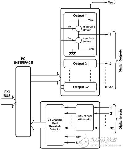
2. Digital I/O module
The outputs of the 40-411, 40-412, and 40-413 are driven by a dc-converter that uses a MOSFET output and includes a current limiter that allows current to pass smoothly. After the drive enters current-limit mode, the voltage drop across the MOSFET, this voltage drop causes the MOSFET to heat up. This driver also includes a temperature sensor that can turn the MOSFET off by protecting the current. When the MOSFET cools, it can start working again. This powerful device protects the device from damage - a sustained high voltage will burn the device. This temperature sensor and current limiter are very close to the MOSFET, so the response time is very short, which effectively protects the MOSFET.
In a digital I/O card that contains both current sinking and sinking current, both drivers can be turned off, or one of the drives can be connected to a power source or grounded.
Where the high level is applied, it should be noted that it contains a biasing diode. When the switch is turned on, it means that there will be a voltage drop across the drive, which is higher than expected. Impedance.
3. Fault injection module
Pickering's fault injection module is used to simulate the types of faults common in systems with high safety requirements. They can be used to simulate open-circuit short-circuit faults, and some common short-circuits with other signal lines or power/ground lines. However, when choosing, you need to look at the specific application, because there are some applications that require switching current or higher voltage requirements, especially for some special applications, which requires the necessary trade-offs from the component level. . The figure below is an illustration of Pickering's fault injection module:

4. Module combination - fault injection module and digital I / O module
In order to connect the power and ground to the path, the user can implement it with a digital I/O module and also provide current limiting protection for the switch. The digital I/O module can be used to transform the switching of the fault injection into a cold switching, which has little effect on the life of the switch.
The classic block diagram of fault injection, as shown in the above diagram, has been integrated with a variety of possible fault signal source interfaces. One or more fault signal sources can be power (battery) or ground. When a digital I/O card is used to connect the middle portion, it can function as a current limit.
If the digital I/O module 40-411 only provides a connection to the ground, it can only drive one source of the excitation signal. If the signal direction is reversed, then 40-411 will compress the signal to 0.6V below ground, because there is a diode in the output. 40-411 is with 1A sink current, it will limit the signal to 1.5A and +3.5V, if it is low voltage, then there will be a high current, the worst case is at 1.5V 3.5A current.
The 40-412 module will provide a drive that allows connection to an external ground or power line. The only requirement is to connect a faulty line to provide this functionality. In the case of a low-level drive (connected to ground), the current is typically limited to 1A, and the worst case is 1.5A at 1.5V. In the case of a high level drive, the current will be approximately 1A, but it should be noted that the voltage drop will be greater than when the low level is driven.
The 40-413 digital I/O module is about the same as the 40-412, but at high currents, the low level drive is typically 7A, and at high levels, 3.5A current. This design is not suitable for 2A current applications, but can be used in fault injection applications that require large currents.
In many cases, the ability to limit more current can be increased by placing more than one channel of digital I/O modules in parallel.
No matter what the situation, the user can switch signals through the digital I/O module card without having to operate through the switch. The switch on the fault injection card can be turned off before the digital I/O module closes the connection to the ground or the excitation source. This means that the life of the switch can be greatly increased because the thermal switching of the switch is converted to a cold switch.
In all cases, the user must ensure that the digital I/O voltage does not exceed the nominal voltage.
5. Other applications
In practical applications, digital I/O can be used not only in the fault injection module, but also in other switch modules connected to the ground or power line.
Jinhu Weibao Trading Co., Ltd , https://www.weibaoxd.com