In the design of switching power supply, the design of power transformer is extremely critical. Especially after the working frequency is increased, it is necessary to achieve the highest power density of the power supply, and it is difficult to meet the better EMC index. The following describes a transformer design method that can greatly improve the EMI noise of the switching power supply.
Due to the existence of parasitic capacitance between the primary side and the secondary side winding, when the transformer is "switched", there is dV/dt at the boundary, and the "quiet layer" is arranged on both sides of the insulating tape, that is, the end side of the primary side and the Vin connected. One end of the secondary side and the ground is disposed on both sides of the insulating tape, which can reduce the dV/dt of the parasitic capacitance at the boundary. Since the drain voltage of the FET is fluctuating, it is wound into the first layer of the skeleton so that the outer layer shields the electromagnetic field emitted by the inner layer. Figures 1 and 2 show two low-noise winding techniques that can be used in a typical flyback converter transformer.

figure 1
Method 1: As shown in Figure 1, the end of the secondary winding connected to the diode must be in close proximity to the insulating tape, so both ends of the insulating tape will have a certain size of dV/dt, but the dV/dt is lower than the drain of the primary winding. The contiguous end is much smaller when adjacent to the insulating tape. The advantage of this transformer is that the "quick end" of the secondary winding is located at the outermost layer, which itself shields the transformer from radiation.
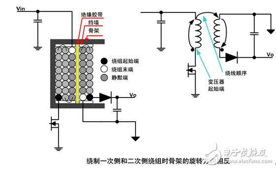
figure 2
Method 2: As shown in Figure 2, the two silent ends are adjacent to the insulating tape. The advantage of this transformer is that the common mode noise across the boundary is reduced, but the external noise of the transformer is relatively large, and the copper shield is required to be wound on the outside. (ie Faraday shielding).

image 3
In the case where the transformer skeleton window has sufficient margin, it is usually necessary to use copper skin "isolation" between the primary side and the secondary side inside the transformer to shield the noise generated by the winding. If the window margin is not sufficient, consider the primary side IC supply winding as a Faraday shield. As shown in FIG. 3, both ends of the winding are AC-coupled to the primary side ground, so that the capacitive noise emitted by the primary side main winding is reduced, and thus the common mode noise conducted to the secondary side is greatly reduced. A disadvantage of using Faraday shields is that the leakage inductance is greatly increased, thereby reducing efficiency. Therefore, we do not generally use any conventional shielding inside the flyback converter transformer, but Faraday shielding is often used.
When designing custom products for customers, the customer requires that CLASS B be transmitted without the addition of peripheral auxiliary circuits. According to Method 1, the traditional "sandwich winding method" not only solves the conduction problem, but also solves the problem. Only the method 1 brings about the problem of large leakage inductance of the transformer, thereby improving the stability of the power supply and meeting the requirements of the customer. The winding sequence of the customized product is shown in Table 1. The conduction result is shown in Figure 4. The peak has a margin of at least 20 dB, and the average has a margin of 10 dB.
Table 1
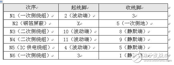
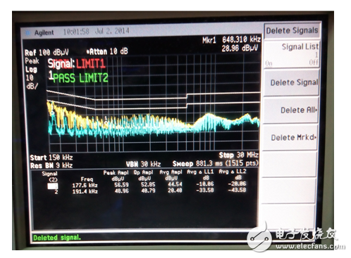
Figure 4
For switching power supplies with transformer topologies, the electromagnetic compatibility (EMC) design of the transformer has a large impact on the EMC level of the entire switching power supply. Normally, the addition of a power line filter is necessary to suppress conducted EMI. However, simply relying on a filter at the input of the power supply to suppress interference tends to result in increased inductance and increased capacitance of the components in the filter. The increase in inductance increases the volume and increases the capacitance by the leakage current safety standard. This paper presents a new transformer design method. It not only reduces the volume of the power line filter, but also has a stronger ability to suppress conducted electromagnetic interference (EMI), and can reduce the manufacturing cost and process complexity of the transformer.
Transparent LED display screen
Transparent Led display is a creative design and upgrade version of Outdoor Led Display screens. It is made by DIP Led strip.
products have features of light weight, energy-saving, high transparency, fast installation and easy maintenance. With advanced and top level of led diode , Priva Led's Outdoor transparent LED Display have low power consumption and high brightness. In this ways, It is very stable and durable during lifetime.


For better understanding Led curtain display main advantages,
High Water-Proof grade applied with IP65 water-proof standard, make your screen working perfectly without problems even in heavy rain.

Light-weight cabinet The cabinet is about 5-8 KG per square meter, 60% less weight compared with traditional tile and have greatly reduce the load bearing pressure of the structures.

High transparency rate Louver design, make the transparency rate up to 72%, and this design greatly satisfied people`s curiosity to see outside from inside.

High brightness8000nits for P25, could be used absolutely for outdoor under strong sunshine.

Fast & easy installation No need steel structure, Solid and simple assemble style, make installation and maintenance quick and easy. It stands firmly even in big wind.

Installation Steps
Installation Steps
1 Fitting the steel structure: fitting it on the wall firmly

2 Attach the U-Tile frame to the structure firmly

3Lock the frame on the structure by screws

4Hanging the upper right hooks of the cabinet to the card slot of the right U-tile Frame.

5
Buckle the left position pins of the cabinet to the location holes of the left side of the U-tile frame

6 Aim at the screw holes for the front service installation, fitting 6 screws on the U-tile frame through the cabinet from the front.
(This is a procedure of front service, this cabinet support also available for back maintenance)


7 Then finished installation for one cabinet. The same as the next cabinet.
8 Cable Connection.
Connect the male-plug (with cable) of the next cabinet to the female-plug of its upper cabinet firmly.

9 Using the same mode to finish the rest connection (five-pins cable), then the installation work for a complete LED display is finished.

After-sale maintenance
1 The cabinet support single trip maintenance. If there any bad LED lamp or damage on single strip, you can remove the strip separately without take out the cabinet and control box.

2, Cabinet support front & back installation and maintenance. If there any problem on single cabinet, you can remove the cabinet from the front & back of the screen.

3 ,If there damages on the control box, you need remove the cabinet and open the cover of the power supply box to do repair & exchange work.

Cabinet size:

Package: Wooden case 1 for 10 led strip curtain cabinets.
Package size:

This outdoor LED Strip curtain display series product are widely used for building facade, behind of glass wall, in front of glass wall, led billboard& signs and on top of building.
Welcome to visit our factory in Nansha Guangzhou China. Please contact us for any questions or inquiries!
Led curtain display Parameter
Model number
Pixel pitch
Pixel configuration
Size of block module
Resolution of module
Density
Cabinet material
Size of cabinet(l*h*t)
Weight of cabinet
Driving method
Best viewing angle
Max power consumption
Colors
Gray scale
Color temperature
Control method
Driving device
Frame frequency
Refresh frequency
Brightness
Working voltage
Working temperature
Out-of control point
Brightness Control
IP grade
Mtbf
Transparency
Led Curtain Display,Outdoor Led Curtain For Building,Led Curtain Wall Display,Led Strip Curtain
Shenzhen Priva Tech Co., Ltd. , https://www.privaled.com