Abstract: For the transmission of pulse signals at a distance of about 100 meters, the transmission characteristics of the signal are first analyzed using transmission line theory, and the delay, attenuation and reflection of the signal transmission are calculated; then the RS-485 serial bus standard and the transmission terminal are used Connect the circuit of matching resistor to transmit the pulse signal, on the one hand, it improves the signal transmission rate and transmission distance, on the other hand, it eliminates the distortion and distortion caused by the reflection of the signal, and enhances the reliability of the signal transmission; Finally, the experiment proves the transmission circuit The structure is simple, the signal transmission reliability is high, and it has great practical and popularization value.
Foreword: In the case of pulse signal transmission at a distance of tens of meters or hundreds of meters, the concept of long-line transmission is introduced according to the high-speed circuit design theory, and the transmission characteristics of the pulse signal are analyzed. In order to ensure the integrity of the pulse signal transmission, the RS-485 serial bus standard and the circuit scheme of the matching resistance are used. Experiments have proved that the scheme proposed here is practical and superior in performance. In addition, the scheme has a simple structure and low cost, and has great reference and use value for the transmission of short-range pulse signals and high-frequency digital signals.
1 Transmission line theory
1.1 Definition of long-term transmission
Under normal circumstances, the harmonic frequency of the edge of the pulse signal is higher than its own frequency, and its rapidly changing rising / falling edge will cause unexpected results in the signal transmission process. According to the definition of high-speed circuit design theory, if the transmission length of the pulse signal is greater than 1/6 of the effective length corresponding to the rising or falling edge time of the signal, the transmission of the signal can be considered as a long-line transmission. In the long-term transmission of the pulse signal, there will be obvious problems such as transmission delay, attenuation and oscillation that affect the signal integrity. This requires the analysis of the transmission line theory.
1.2 Transmission characteristics of pulse signals
Transmission line theory is a distributed parameter circuit theory. All positions on the line are composed of distributed resistance R, distributed capacitance C, distributed inductance L and distributed conductance G.
These distribution parameters determine the transmission characteristics of pulse signal long-line transmission.
The characteristic impedance of the signal transmission line is expressed by the ratio of the incident voltage to the incident current on the transmission line. The general expression is:
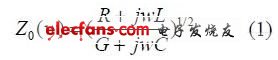
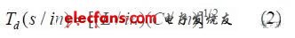
The transmission delay of the signal is determined by the series inductance and parallel capacitance in the distribution parameters of the transmission line. The transmission delay d T per unit length of the transmission line is expressed as:
The overall transmission of the pulse signal on the transmission line is shown in Figure 1, where SZ is the source impedance, 0 Z is the transmission line impedance, and LZ is the load impedance.

Figure 1 The characteristics of the pulse signal in the transmission line
In Figure 1, XH w represents the attenuation function of the signal through the transmission line; A (w) and 1R (w) represent the input reception function and reflection function at the source end of the transmission line; T (w) and 2R (w) represent the transmission function of the transmission line terminal And reflection function, the expressions are as follows:
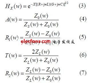
It can be seen from the above expression that if the characteristic impedance of the transmission line does not match the source impedance and the terminal load, the transmission signal will be reflected at the impedance discontinuity, and the reflected signal will go back and forth multiple times until the attenuation is zero. The superposition of signals causes distortion and ringing of the transmitted signal.
1.3 Calculation of transmission line distribution parameters
In summary, the transmission characteristics of the signal are mainly determined by the distribution parameters of the transmission line. As long as the partial parameters of the transmission line and the source and terminal impedance values ​​are determined, the transmission characteristics of the signal can be calculated according to equation (1-7). Taking twisted pair as an example, the calculation of its characteristic parameters can be calculated as follows:
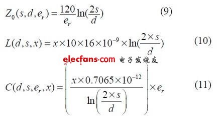
Where d is the diameter of the transmission line conductor, s is the distance between the two lines, and re is the effective relative dielectric constant. For the calculation of the distribution parameters of other types of transmission lines, please refer to [5-6].
2 Pulse signal transmission scheme and experimental test
When the pulse signal is transmitted over a long distance, in order to ensure the transmission rate and reliability of the signal, the RS-485 serial bus standard is adopted to drive and receive the signal.
2.1 RS-485 bus standard
The RS-485 standard is a multi-point, bidirectional communication link based on a single pair of balanced lines, providing a high noise suppression, high transmission rate, long transmission distance, wide common mode range, and low-cost transmission platform [7]. This solution uses the MAX485 chip that complies with the RS-485 standard to build the driving and receiving circuits. One of the chips is fixed for transmission, and the other chip is fixed for reception. The corresponding transmission and reception ports of the two chips are connected with equal length twisted pairs.
2.2 Analysis of pulse signal transmission characteristics
The transmission characteristics of the pulse signal on the twisted pair are determined by its transmission line distribution parameters and the output impedance of the driving chip and the input impedance of the receiving chip.
The actual measured diameter of the twisted pair used is 0.05 cm, s is 0.096 cm, and re takes a constant 2.5 between the dielectric constant of the line insulator and the air dielectric constant (1.00). The characteristic impedance of the twisted pair is calculated from equation (9-11). The distributed inductance and distributed capacitance per inch are:
![]()
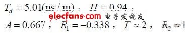
It is also known that the output resistance of the MAX485 chip driver is about 50 Ω, and the input resistance at the receiving end is greater than 12 kΩ. From the formula (1-7), the unit transmission delay d T of the transmission line, the attenuation function H of the transmission line, and the function values ​​A, T, 1 R and 2 R of the transmission line source and terminal are respectively:
The transmission twisted pair length is 65 m, and the pulse signal amplitude is +4 V. It can be calculated that the delay of the signal through the twisted pair is 325.65 ns; the amplitude of the signal reaching the receiving end is 4 & TImes; AHT = 5.02 V; the amplitude of the generated reflected signal reaches 22 4 & TImes; AH R = 2.36 V after attenuation transmission. The signal will continue to reflect at the source, and so on until the attenuation is zero. Use the oscilloscope to directly measure the waveforms of the MAX485 driver chip output and the receiver chip input port as shown in Figure 2.
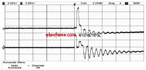
Figure 2 The waveform of the A port of the sending and receiving chip when there is no termination
The time axis gear is 2 us per division, and the signal amplitude gear is 2 V per division.
It can be read that the input pulse signal amplitude is +4 V, the signal transmission delay is about 320 ns, the positive amplitude of the receiving pulse signal is +5.3 V, and the negative amplitude is -1.8 V. In summary, the results measured with an oscilloscope are basically consistent with the theoretical analysis.
When a 100 Ω resistor is connected across the receiving end, the load of the twisted pair terminal is approximately 100 Ω, which matches the characteristic impedance of the transmission twisted pair. At this time, 2 R ≈ 0 and T ≈ 1 can be calculated, and the remaining parameters are the same as above. Keeping the distance of the twisted pair transmission and the amplitude of the transmission signal unchanged, it can be calculated that the transmission delay of the pulse signal is 325.65 ns, the amplitude of the signal at the receiving end is 2.668 V, and the terminal does not generate a reflected signal. The waveforms of the output of the sending chip and the input of the receiving chip are measured with an oscilloscope as shown in Figure 3 (a). The input signal amplitude is +4 V, the signal delay at the receiving end is about 318 ns, and the amplitude is +2.74 V; The signal waveform of the signal at the sending end and the receiving end of the circuit. The transmission delay of the signal is 400 ns, of which the delay is about 320 ns on the transmission line, and the internal delay of the sending and receiving chips is about 40 ns, respectively. Keep consistent with pulse width.
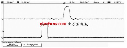
(A) Waveform of A port of sending and receiving chip
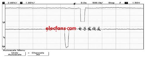
(B) Waveforms of signals at the sending and receiving ends
Figure 3 The waveform of a twisted pair terminal connected to a 100 Ω resistor
To sum up, it can be seen that for the transmission of pulse signals through long lines, it is completely correct to use the transmission line theory for analysis. For the distortion and oscillation of the pulse signal during long-line transmission, the reflection of the transmission signal at both ends of the transmission line can be eliminated by connecting a resistor in series at the source end of the transmission line or paralleling a matching resistor at the terminal.
When the distance between the two ends of the transmission and reception is far away or the communication rate is high, it is also necessary to connect a bias resistor at both ends of the transmission line to set the level when there is no data on the transmission line to 0 level to reduce the reception caused by interference or signal reflection Terminal misoperation.
3 Conclusion
The experiment proves that the transmission circuit composed of MAX-485 chip can effectively eliminate the attenuation and interference of the signal in the transmission, and the stability and integrity of the signal transmission can be well maintained by terminating the matching resistor.
Board to Board Connectors
Board to Board Connectors
ATKCONN ELECTRONICS CO., LTD , https://www.atkconn.com