The hardware circuit design uses a DSP chip and peripheral circuits to form a speed capture circuit. The motor drive controller uses a micro control chip and peripheral circuits to form circuits such as current sampling, overcurrent protection, and pressure regulation. CPLD is used to implement the rotor position of the brushless DC motor The logical commutation of the signal. Racing brake controller is composed of anti-skid controller and motor drive controller. Both controllers are based on DSP chips. The anti-skid controller is mainly based on the slip rate as the control object, outputting the given brake pressure, using the DSP chip as the CPU, plus the racing and wheel speed signal conditioning circuit. The motor drive controller mainly adjusts the size of the brake pressure and controls the motor current. The DSP chip is also used as the CPU, and the peripheral circuit motor current feedback conditioning circuit, overcurrent protection circuit, brake pressure conditioning circuit, four sets of three-phase full bridge The inverter circuit etc. constitute a motor drive controller.
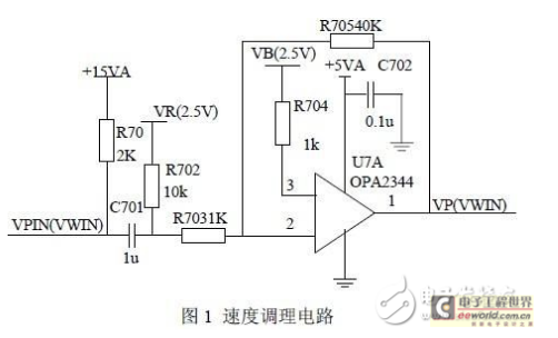
Signal processing circuit: The anti-skid controller of the racing car is mainly used to control the slip rate to prevent the car from slipping. The pressure reference value is output after the deviation of the slip rate is adjusted to track the given slip rate. The anti-skid controller must have a conditioning circuit for the speed signals of the front wheels and brake wheels of the racing car, mainly to obtain the feedback slip rate. The speed signal of the racing car is replaced by the speed signal of the front wheel of the free-running racing car. Speed ​​sensors are installed on the front wheels and brake wheels of the racing car. When the wheels rotate, the speed sensors will generate an AC signal in the form of a sine wave. Each time the wheel turns, the speed sensor will send a 50-cycle sine AC signal. The amplitude of the sinusoidal AC signal changes with the speed of the wheel. The signal is a sine wave signal with a bias voltage of 2.5V, a peak value of 0.3V, and a maximum signal amplitude of no more than 5V.
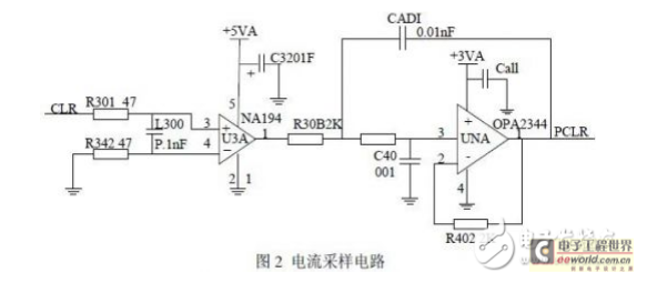
Current sampling and overcurrent protection circuit: The current of the brushless DC motor is detected by the resistance on the bus of the power drive circuit. The resistance above the bus is connected in parallel by two 0.01Ω power resistors. The sampling circuit uses these two parallel sampling resistors to conduct current sampling. The sampling resistor converts the current signal into a voltage signal. The voltage signal is sent to the current monitoring chip for amplification Then, it is filtered by the second-order active filter circuit formed by OPA2344, and finally the current feedback signal is directly sent to the A/D converter.
The hardware overcurrent protection circuit plays an important role in the normal operation of the system, mainly to protect the power device MOSFET and the motor. The system also has a software protection function. The overcurrent signal OVCURX is sent to the input pin of the DSP. When OVCUR is high, the DSP will generate a motor control rotation signal ENABLE to turn off the logic signal and stop the motor. The chip IR2130 has its own over-current protection function.
Completed the design of the racing brake control system, mainly the hardware design and control strategy research. In terms of design, high-speed DSP chips and CPLDs are used and their peripheral circuits are designed. The system also designs a driving circuit with IR2130 as the core, a current signal hardware amplifier circuit, a filter circuit and a protection circuit, a pressure signal amplifier circuit and a filter circuit, a racing circuit and a wheel speed processing circuit, and so on. The control strategy uses fuzzy control to adjust PID parameters.
Ningbo Autrends International Trade Co.,Ltd. , https://www.vapee-cigarettes.com