This article is mainly about the related introduction of tms320c6000, and emphasizes on the tms320c6000 series dsp programming tool and guideline to carry on the detailed elaboration.
dspDSP (digital singnal processor) is a unique microprocessor, a device that processes a large amount of information with digital signals. Its working principle is to receive an analog signal, convert it to a digital signal of 0 or 1, then modify, delete, and strengthen the digital signal, and interpret the digital data back to analog data or actual environment format in other system chips. It not only has programmability, but its real-time operating speed can reach tens of millions of complex instruction programs per second, and its source exceeds that of general-purpose microprocessors. It is an increasingly important computer chip in the digital electronic world.
Its powerful data processing capabilities and high operating speed are the two most commendable features. DSP is either the abbreviation of Digital Signal Processing (the theory and methods of digital signal processing) or Digital Signal Processor (programmable microcomputer for digital signal processing). Processor) abbreviation. What we call DSP technology, generally refers to the method and technology that use general-purpose or special-purpose DSP processor to finish digital signal processing. DSP has the following characteristics: DSP processor adopts Harvard structure and improved Harvard structure. The Harvard structure is to separate the storage space of program code and data, each with its own address and data bus. The reason why the Harvard structure is adopted is to process instructions and data in parallel, which can greatly increase the speed of calculations. In order to further improve the efficiency of signal processing, improvements have been made on the basis of the Harvard structure. It is called an improved Harvard structure to enable data transmission between the program code and the data storage space. Using pipelining technology. Pipelining technology is to overlap the various steps of each instruction to execute.
The Harvard structure that separates the address of the program storage space and the data storage space from the data bus adopted by the DSP processor provides great convenience for the use of pipeline technology. In order to improve the operation speed of DSP processors, they have set up hardware multipliers without exception, and MAC (multiply and accumulate) instructions. DSP processors have set up a completely independent bus and controller for DMA, which is very different from a general-purpose CPU. Its purpose is to carry out data transmission without affecting the work of the CPU and its related buses. In the DSP processor, a special data address generator is set up to generate the required data address. The generation of the data address is parallel to the work of the CPU, thereby saving the time of the CPU and improving the processing speed of the signal. The DSP processor works in coordination with the external environment for its own work needs. A wealth of peripherals are often set up. Such as a clock generator. Timer etc.
Fixed-point DSP processors and floating-point DSP processors. Overflow issues are often considered in fixed-point DSPs, while floating-point DSPs can basically be ignored. Compared with fixed-point DSP processors, floating-point DSP processors are faster, especially for floating-point operations. In occasions where real-time requirements are very high. Often consider floating-point DSP processors. The price of floating-point DSP processors is relatively high and development is more difficult. The purpose of DSP 2000 is mainly used for control: power supply, optical network, etc. 5000 is communication and still image processing: video products, digital radio, etc. And 6000 is digital communication and image processing: mobile communication, printers, digital scanners, etc.
dsp programming1. DSP programming
The Linux file interface function is used to program the OSS driver sound card, as shown in Figure 17.5. The operation of the DSP interface generally includes the following steps:
â‘ Open the device file /dev/dsp.
The mode used to operate the sound card must also be specified when opening the device. For sound cards that do not support full-duplex, it should be opened in read-only or write-only mode. Only those sound cards that support full-duplex can be read The writing mode is opened, which also depends on the specific implementation of the driver. Linux allows the application to open or close the device file corresponding to the sound card multiple times, so that it can easily switch between the playback state and the recording state.
â‘¡ If necessary, set the buffer size.
The sound card driver running in the Linux kernel maintains a buffer, whose size will affect the effect of playback and recording, and its size can be appropriately set using the ioctl() system call. It is not necessary to adjust the buffer size in the driver. If there is no special requirement, the default buffer size is generally sufficient. If you want to set the size of the buffer, you should usually follow the opening of the device file, because other operations on the sound card may cause the driver to be unable to modify the size of the buffer.
â‘¢ Set the number of channels.
According to the specific conditions of the hardware device and driver, it can be set to mono or stereo.
â‘£ Set the sampling format and sampling frequency
Sampling formats include AFMT_U8 (unsigned 8 bits), AFMT_S8 (signed 8 bits), AFMT_U16_LE (little endian mode, unsigned 16 bits), AFMT_U16_BE (big endian mode, unsigned 16 bits), AFMT_MPEG, AFMT_AC3, etc. Use the SNDCTL_DSP_SETFMT IO control command to set the sampling format.
For most sound cards, the supported sampling frequency range is generally 5kHz to 44.1kHz or 48kHz, but it does not mean that all continuous frequencies in this range will be supported by the hardware. The most commonly used in audio programming under Linux Several sampling frequencies are 11025Hz, 16000Hz, 22050Hz, 32000Hz and 44100Hz. Use the SNDCTL_DSP_SPEED IO control command to set the sampling frequency.
⑤ Read and write /dev/dsp to realize playback or recording.
Figure 17.5 OSS dsp interface user space operation process
The program in code listing 17.3 implements the process of sound recording and playback using the /dev/dsp interface. Its function is to first record a few seconds of audio data, store it in the memory buffer, and then play it back.
Code list 17.3 OSS DSP interface application programming example
1 #include
2 #include
3 #include
4 #include
5 #include
6 #include
7 #include
8 #define LENGTH 3 /* Store the number of seconds*/
9 #define RATE 8000 /* Sampling frequency*/
10 #define SIZE 8 /* Number of quantization bits*/
11 #define CHANNELS 1 /* Number of channels*/
12 /* Memory buffer for saving digital audio data*/
13 unsigned char buf [LENGTH *RATE * SIZE * CHANNELS / 8];
14 int main()
15 {
16 int fd; /* The file descriptor of the sound device*/
17 int arg; /* Parameter used for ioctl call*/
18 int status; /* The return value of the system call*/
19 /* Turn on the sound device*/
20 fd = open("/dev/dsp", O_RDWR);
21 if (fd << 0)
twenty two {
23 perror("open of /dev/dsp failed");
24 exit(1);
25}
26 /* Set the number of quantization bits during sampling*/
27 arg = SIZE;
28 status = ioctl(fd, SOUND_PCM_WRITE_BITS, &arg);
29 if (status ==-1)
30 perror("SOUND_PCM_WRITE_BITS ioctl failed");
31 if (arg!= SIZE)
32 perror("unable to set sample size");
33 /* Set the number of channels during sampling*/
34 arg = CHANNELS;
35 status = ioctl(fd, SOUND_PCM_WRITE_CHANNELS, &arg);
36 if (status ==-1)
37 perror("SOUND_PCM_WRITE_CHANNELS ioctl failed");
38 if (arg!= CHANNELS)
39 perror("unable to set number of channels");
40 /* Set the sampling rate*/
41 arg = RATE;
42 status = ioctl(fd, SOUND_PCM_WRITE_RATE, &arg);
43 if (status ==-1)
44 perror("SOUND_PCM_WRITE_WRITE ioctl failed");
45 /* Loop until Control-C is pressed */
46 while (1)
47 {
48 printf("Say something:");
49 status = read(fd, buf, sizeof(buf)); /* recording*/
50 if (status!= sizeof(buf))
51 perror("read wrong number of bytes");
52 printf("You said:");
53 status = write(fd, buf, sizeof(buf)); /* play sound*/
54 if (status!= sizeof(buf))
55 perror("wrote wrong number of bytes");
56 /* Wait for the playback to end before continuing to record*/
57 status = ioctl(fd, SOUND_PCM_SYNC, 0);
58 if (status ==-1)
59 perror("SOUND_PCM_SYNC ioctl failed");
60}
61}
tms320c6000 series dsp programming tool and guide1. Why process signals digitally?
(1) The analog circuit is composed of analog components: resistance, capacitance and inductance, etc. These components will dynamically affect the effect of the analog circuit with changes in voltage, temperature or mechanical structure;
(2) The digital circuit has good noise suppression capability, less development time and power consumption
Although digital circuits have so many advantages, in some cases analog circuits must be used: very high frequency signals (>100MHz). There are two reasons: (1) the limitation of ADC conversion; (2) it is difficult to process very high frequency signals in real time using digital circuits.
2. Why use DSP?
DSP is the abbreviation of Digital Siginal Processor.
(1) Compared with high-end processors on PCs, it has lower power consumption
(2) Compared with high-end processors on PCs, it has a lower price
Therefore, it is a better choice to use DSP when considering price, mechanical size, low power consumption and "high frequency" processing.
Compared with embedded ARM, DSP has greater advantages in signal processing, and ARM prefers control.
3. Tipically DSP Algorithms?
In most DSP algorithms, the sum of product (SOP) is the most basic unit.
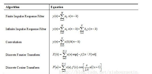
DSP optimizes multiplication and addition. Multiplication and addition are generally completed in one instruction cycle on DSP, which is why DSP is suitable for signal processing.
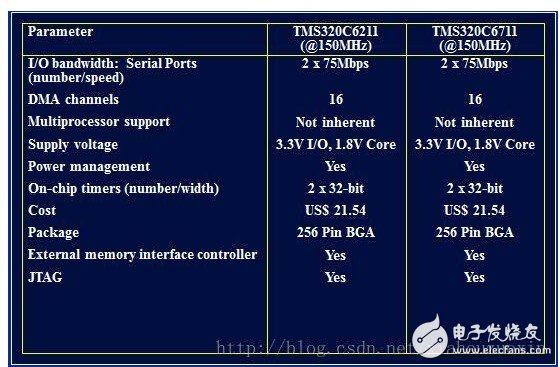
4. Choose a DSP
Through the data sheet, the list compares the two parameters, such as
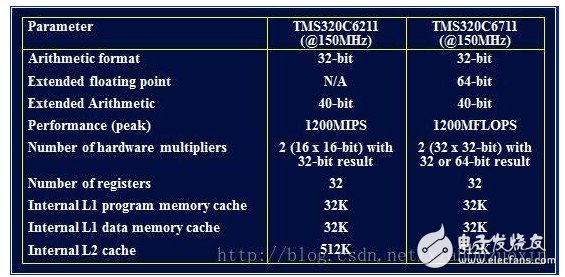
Floating-point DSP and fixed-point DSP use situation comparison:
Floating-point DSP is generally used for high precision, wide dynamic range, high signal-to-noise ratio, and is generally easier to use. Fixed-point DSP has lower power consumption, is cheaper, and is relatively smaller in size.
5. DSP and ASIC (Application Specific Integrated Circuit)
ASIC sounds more high-end, but there are fewer applications, mainly because ASIC development cycle is long (at least about 1 year), poor flexibility (once the tape-out is not changed), and expensive. Unless the modules you frequently use are made into tape-out reuse, ASICs are generally not used in product development.
6. TMS320 series DSP
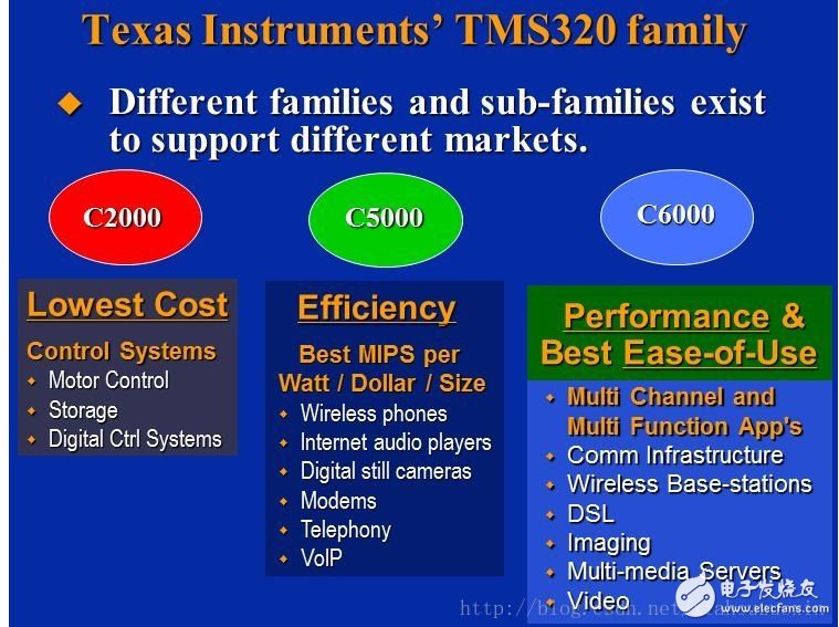
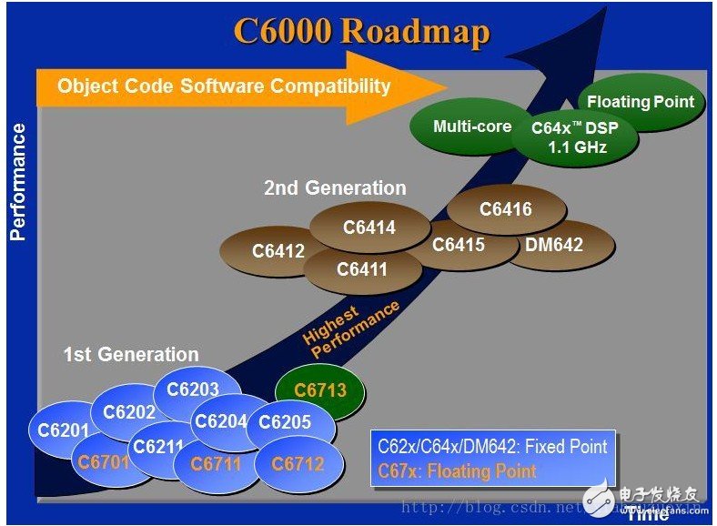
TI C6000 series are mainly divided into C64x, C62x, C67x three sub-series, C62x and C64x are fixed-point DSP, C67 series are floating-point DSP.
ConclusionThis is the end of the related introduction about tms320c6000. Please correct me if there are any deficiencies.
Related reading recommendation: write a DSP program based on assembly (ASM) language
Related reading recommendations: how to get started with dsp28335: programming steps
Led Floor Panels,Led Dance Floor Panel,48W Led Light Panel,Floor White Uplight Panel Led
Kindwin Technology (H.K.) Limited , https://www.szktlled.com