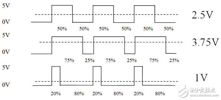
PulseWidthModulation pulse width modulation, referred to as PWM.
PWM (Pulse Width Modulation) A method of digitally encoding the analog signal level. The computer can only output a digital voltage value of 0 or 5V and cannot output an analog voltage. If we want to obtain an analog voltage value, we must use high resolution. A rate counter that changes the duty cycle of the square wave to encode the level of an analog signal.
The digital signal is still output because the full-scale DC power supply is only 5V (1) and 0V (0). The voltage is clamped to the analog load by a repetitive pulse sequence of connection (1) or disconnection (0). The connection is the DC supply output, and the disconnection is the DC supply disconnection. By controlling the connection and disconnection time, as long as the bandwidth is sufficient, an analog voltage of not more than the maximum voltage value can be output.
The microcontroller used is STC89C52, which has three 16-bit Timers, which are T/C0, T/C1, and T/C2. The function of Timer can be controlled by configuring related registers.
Controlling the PWM requires a timer to generate waveforms of different duty cycles, using a timer interrupt.
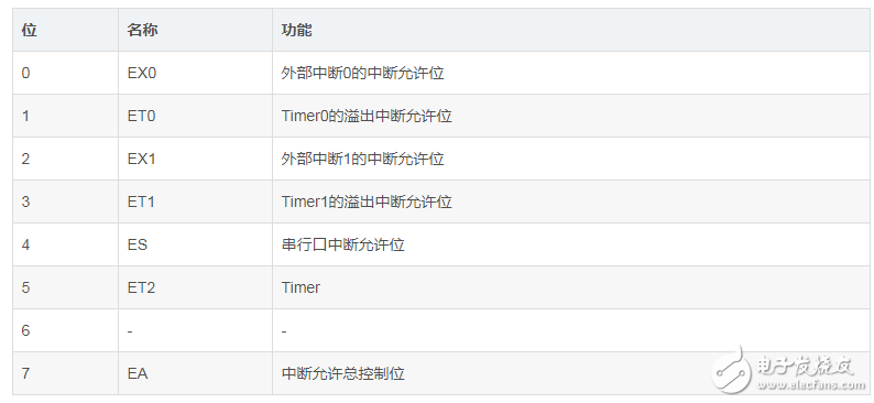
Related registers:
1.IE register
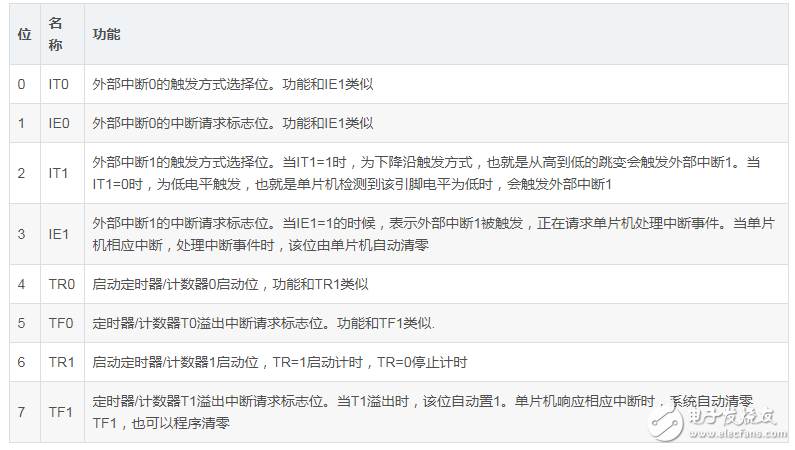
2. TCON register
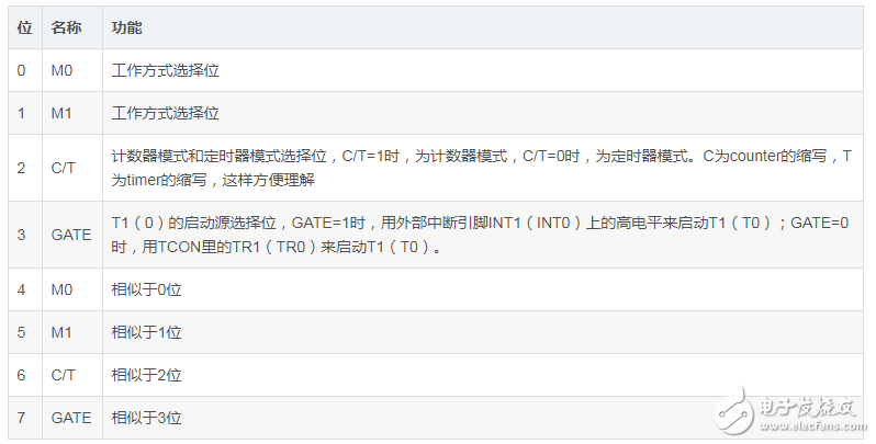
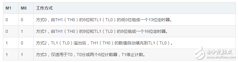
3. TMOD register
Control how Timer0/1 works
4. Timer0/1 count register
TL0
TL1
TH0
TH1
When the timing is turned on, TL0 (TL1) automatically follows the machine cycle plus one. When TL0 (TL1) is full, it will automatically clear and enter one bit to TH0 (TH1) without manual operation.
When both TL0 (TL1) and TH0 (TH1) are full, if the timer interrupt and the total interrupt are both turned on, an overflow interrupt will occur and the two registers will be cleared.
Use PWM to complete the breathing light hardware circuit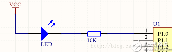
Unsigned char PWM_COUNT; //count
Unsigned int HUXI_COUNT; //duty cycle update time
Unsigned char PWM_VLAUE; //duty ratio comparison value
Bit direc_flag; //Duty cycle update direction
Void timer0_init()
{ TMOD=0x02; //Mode setting, 00010000, Timer 0, working in mode 2 (M1=1, M0=0)
TH0=0x47; //The timer overflow value is set, and an interrupt is initiated every 200us.
TL0=0X47; TR0=1; //Timer 0 starts timing
ET0=1; //Open timer 0 interrupt
EA=1; //open total interruption
PWM_COUNT =0; }
Void time0() interrupt 1
{ PWM_COUNT++; HUXI_COUNT++;
If(PWM_COUNT == PWM_VLAUE) //Whether it is time to light the LED
LED = 1; //Light the LED
If(PWM_COUNT == 10) //The current period ends
{ LED = 0; //extinguished LED
PWM_COUNT = 0; //retime}
If((HUXI_COUNT == 600) && (direc_flag == 0)) { //duty cycle increases by 10%
HUXI_COUNT = 0;
PWM_VLAUE++; if(PWM_VLAUE == 9) //Duty change direction
Direc_flag = 1;
}
If((HUXI_COUNT == 600) && (direc_flag == 1))
{ //Duty cycle reduced by 10%
HUXI_COUNT = 0;
PWM_VLAUE--;
If(PWM_VLAUE == 1) //Duty change direction
Direc_flag = 0;
}
}
Void main()
{ HUXI_COUNT = 0;
PWM_COUNT = 0;
PWM_VLAUE = 5;
Direc_flag = 0;
LED = 1; //Default LED is off
Timer0_init(); //Timer 0 initialization
While(1);
}
RAM/RFM Intermediate Frequency Capacitors
RAM/RFM intermediate frequency capacitors
Intermediate Frequency Capacitors,Induction Heating Capacitors,Furnace Resonant Capacitor
YANGZHOU POSITIONING TECH CO., LTD. , https://www.cndingweitech.com