With the increasing environmental pollution and economic crisis in the world, research on renewable energy has received more and more attention. As the most promising converter to generate renewable energy, grid-connected technology has become the focus of research. Among them, phase-locked technology is its core technology.
Commonly used phase locks are hardware phase lock and software phase lock. The traditional hardware phase lock is the zero-crossing detection of the voltage signal through the logic device. The circuit is simple and the design is ingenious, but it has some shortcomings. When the grid voltage frequency, phase abrupt or three-phase voltage imbalance, it is difficult to achieve phase locking. Poor performance. The software phase lock has good anti-interference ability, and can achieve phase locking with higher precision and faster speed.
Therefore, based on the analysis of the basic principle of phase-locked loop, this paper builds a grid-connected test platform and adopts software lock-in technology with free design and adaptability. The experiment shows that the soft phase-locking technology can achieve phase lock well.
1 Basic principle of phase-locked loop
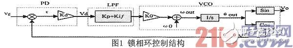
The phase-locked loop is a phase error feedback system consisting of a phase detector (PD), a low-pass filter (LPF) and a voltage-controlled oscillator (VCO). Its working principle is to phase the input voltage signal with the internal signal of the SPLL. The difference is converted into a direct current amount, and after passing through the filter, the voltage and phase of the signal are adjusted by the voltage-controlled oscillator, so that it is in phase with the grid voltage at the same frequency, and its control structure diagram is shown in FIG.
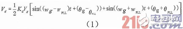
Wherein, the phase detector adopts a multiplier to form a closed loop phase-locked loop based on the multiplier phase detector, and compares the output signal v0 of the voltage controlled oscillator with the input signal vg to generate an error voltage vd of the phase difference.
Phase detector output type (1):
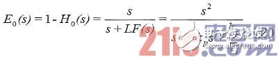
It can be found in the above equation that there is a high frequency component in the phase difference of the phase detector output, so it is necessary to filter the high frequency component through the low pass filter. The low-pass filter is actually a proportional-integral controller PI, which filters out the second harmonic component and noise in the error voltage vd to ensure the stability of the system. The output of the error transfer function of the PI controller is expressed as equation (2). .
The voltage-controlled oscillator plays an integral role in the phase-locked loop, that is, the voltage-controlled oscillator is actually an integral integral link in the phase-locked loop, completing the voltage/frequency conversion.
2 hardware circuit design
2.1 DSP28335 brief introduction
The DSP chip used in this paper is TMS320F28335, which has a 12-bit analog-to-digital converter with pipeline structure and 6 independent ePWM modules. The ADC has 16 channels and 1 conversion core for sequential sampling and simultaneous sampling. A complete ePWM output channel consists of two signals, EPWMxA and EPWMxB. The IPM module drive signals in the experimental system are generated by this module.
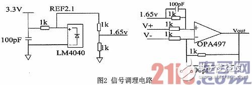
2.2 Signal Conditioning Circuit
In this design, the Hall voltage sensor VSM025 is used to sample the AC voltage, and the collected grid voltage is converted to between -3 and +3V. At the same time, the voltage signal output by the sensor is differentially amplified and up-regulated by the signal conditioning circuit, and output. The 0~3V voltage signal is collected and processed by the AD sampling of the DSP. Its signal conditioning circuit is shown in Figure 2.
2.3 signal output circuit
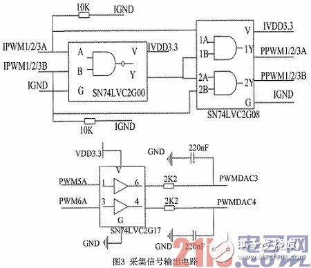
The PWM signal is a series of pulse signals with variable pulse widths. The output can be used to characterize the analog signal. Integration at the PWM output can be used to obtain the desired analog signal. The PWM wave generated in this system drives the IPM module through the logic chip, and the waveform output is observed through the RC low-pass filter circuit to the PWM DAC port. Its circuit diagram is shown in Figure 3.
3 software algorithm design
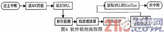
In the grid-connected power generation system, the voltage phase of the grid is locked by the phase-locking technology, so that the current of the inverter output is in phase with the grid voltage. The control accuracy of the phase-locked technology directly affects the performance of the grid-connected operation. The flow chart of the software phase lock is shown in Figure 4.
4 Experimental verification
4.1 Verify with PWMDAC
In order to verify the effect of software lock-in, an experimental platform was built. The platform consists of six parts: analog grid, voltage sensor, signal conditioning circuit, DSP (TMS320F28335) core board, signal output circuit and digital oscilloscope, as shown in Figure 5.
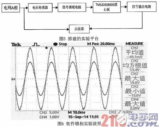
The voltage of one phase of the three-phase voltage of the power grid is detected by the Hall voltage sensor, and the collected signal is processed by the signal conditioning circuit, then sampled by the AD port of the DSP, and phase locked in the DSP, and passed through the PWM port. The RC filter circuit performs the output. Observe the effect of phase lock by observing the output waveform of the PWMDAC port and the grid voltage waveform through a digital oscilloscope.
The oscilloscope observation waveform is shown in Figure 6. The voltage of the analog grid in the system is 18V, as shown by the blue line (top), and the green line (bottom) is the output voltage of the PWMDAC port. Through observation, it can be found that the waveform of the PWMDAC is consistent with the phase of the grid voltage, which perfectly realizes the locking of the voltage phase of the grid.
4.2 Grid verification
On the basis of software phase lock, the grid-connected experimental platform is built, including three-phase analog power grid, voltage sensor, signal conditioning circuit, DSP (TMS320F28335) core board, IPM module, three-phase inductor, current sensor and digital oscilloscope. 7 is shown. Among them, the IPM module uses Mitsubishi's PS21765 module, and the IPM integrates logic, control, detection and protection circuits. The inductance of the three-phase inductor is 7mH. The current sensor detects the output current signal, and its signal conditioning circuit is the same as the voltage.
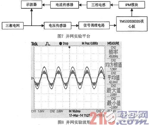
The PWM signal generated by the DSP is driven by the logic circuit to drive the IPM of Mitsubishi Corporation. When the network is connected to the network, the phase-locked waveform and the output voltage are observed first, and the grid is connected under the premise of satisfying the condition. The waveform of the grid connection result is shown in Figure 8. The red line is the output current waveform, and the blue line is the grid voltage waveform after passing the sensor.
It is observed that the output current of the grid-connected inverter and the grid voltage phase are the same, thereby achieving phase locking and grid-connecting of the inverter.
5 Summary
Based on the theory of software phase-locking, this paper designs and implements a phase-locked loop based on DSP technology, which solves the problem of low precision and poor accuracy of traditional hardware phase-locking. It is verified by PWMDAC and actual grid connection. The experimental results show that the method is simple and feasible and has good practical value.
Yuhai company offer custom services including piezo ceramic elements and piezo transducers, Yuhai people work closely with individual customers to provide solutions. We offer engineering support services including material selection, component design assistance, device and system modeling and failure analysis.
We hope to be your best supplier with the elements of superior performance and reliability, lowest prices, most rapid delivery times and the best customer service.

Ultrasonic Transducer,Piezo Transducer,Ultrasonic Distance Sensor,Piezoelectric Transducer
Zibo Yuhai Electronic Ceramic Co., Ltd. , https://www.yhpiezo.com