Liquid level control is a common process control in the industry, and its impact on production cannot be ignored. The single-capacity liquid level control system has characteristics of nonlinearity, hysteresis, coupling, etc., and can well simulate industrial process characteristics. For the liquid level control system, the conventional PID control adopts fixed parameters, it is difficult to ensure that the control adapts to the system's parameter changes and working condition changes, and the ideal effect is not obtained. The fuzzy control has the characteristics of being insensitive to parameter changes and robust. However, the control accuracy is not ideal. If the fuzzy control and the traditional PID control are combined, the fuzzy control theory can be used to adjust the proportional, integral and differential systems of the PID controller to better adapt to the changes of the parameters of the control system and the changes of working conditions. This article brings you a design of a single tank water level control system.
Liquid level controlIn this design, the water tank of the liquid level control system is taken as the research object, the liquid level of the water tank is the controlled quantity, and the outlet valve is selected as the actuator of the control system. In this design, the water level of the water tank is first detected by the differential pressure sensor; the actual value of the water level is A/D converted by the A/D converter, and then converted into a digital signal, which is input into the computer; finally, in the computer, according to the water level setting value and The difference between the actual output values, the PID program algorithm is used to obtain the output value, and then the output value is transmitted to the analog signal through the D/A converter to control the AC frequency converter, thereby controlling the motor speed, thereby forming a closed loop system and realizing the water level computer. Automatic control.
Design principleThe single tank water level setting control system is as follows:
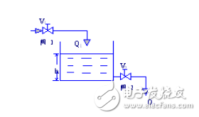
System structure diagram
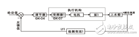
Water tank single capacity liquid level setting control system
The structural diagram and block diagram of this experimental system are shown in the figure. The controlled amount is the liquid level of the upper tank, and the experiment requires that its liquid level be stable at a given value. The liquid level signal of the upper tank detected by the pressure sensor is used as a feedback signal, and the difference between the measured value and the given amount is controlled by the regulator to control the opening degree of the pneumatic regulating valve to achieve the purpose of controlling the liquid level of the water tank. In order to achieve the system without static control under step reference and step disturbance, the regulator of the system should be PI or PID control.
MCGS configuration software designThe MCGS configuration software is used to establish a single tank water level setting control system. The following is part of the process: entering the MCGS configuration environment. Select New Project menu item in the menu file to generate a new project.
The main contents include: defining the project name, the cover window name, and the name of the startup window (the window displayed after the cover window exits), specifying the name of the save database file and the save database, and setting the animation refresh period. After this step, in the MCGS configuration environment, a five-part engineering structure framework is established. The cover window and the startup window can also be created after the user window is created.
Newly built project, the project needs to be stored in the directory of the MCGS subdirectory WORK, otherwise the project will not run.
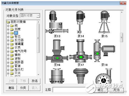
Add object components:
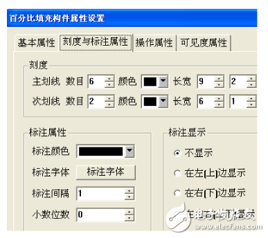
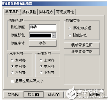
Add a percentage to populate the build and modify its properties:
Add button build:
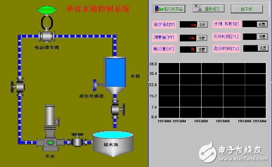
After the project is configured, the final rendering is as follows:
Incremental encoders provide speed, direction and relative position feedback by generating a stream of binary pulses proportional to the rotation of a motor or driven shaft. Lander offers both optical and magnetic incremental encoders in 4 mounting options: shafted with coupling, hollow-shaft, hub-shaft or bearingless. Single channel incremental encoders can measure speed which dual channel or quadrature encoders (AB) can interpret direction based on the phase relationship between the 2 channels. Indexed quadrature encoders (ABZ) are also available for homing location are startup.
Incremental Encoder,6Mm Solid Shaft Encoder,Hollow Rotary Encoder,Elevator Door Encoder
Jilin Lander Intelligent Technology Co., Ltd , https://www.jilinlandermotor.com