First, STM32 interrupt grouping:
Each GPIO of the STM32 can be configured as an external interrupt trigger source, which is also the power of the STM32. STM32 divides many interrupt trigger sources into different groups according to the serial number of the pins. For example: PA0, PB0, PC0, PD0, PE0, PF0, PG0 are the first group, and so on, we can get a total of 16 Group, STM32 stipulates that there can only be one interrupt trigger source working in each group at the same time, then the 16 most external interrupts are working. The STM32F103's interrupt controller supports 19 external interrupt/event requests. Each interrupt has a status bit, and each interrupt/event has separate trigger and mask settings. The 19 external interrupts of the STM32F103 are:
Line 0~15: Input interrupt corresponding to external IO port. 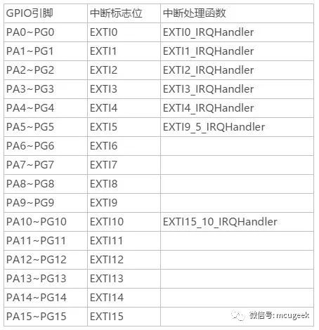 Line 16: Connect to the PVD output.
Line 17: Connect to the RTC alarm event.
Line 18: Connect to a USB wakeup event.
Second: the configuration process of the external interrupt:
1. Configure the trigger source GPIO port:
Because the GPIO port is used as the trigger source, the GPIO port is configured as an input mode. The trigger modes are as follows:
a.GPIO_Mode_AIN, analog input (ADC analog input, or low power consumption)
b.GPIO_Mode_IN_FLOATING, floating input
c.GPIO_Mode_IPD with pull-down input
d.GPIO_Mode_IPU with pull-up input
GPIO_InitTypeDef GPIO_InitStructure; / / define the structure
RCC_APB2PeriphClockCmd (RCC_APB2Periph_GPIOE, ENABLE); / / enable the clock
GPIO_InitStructure.GPIO_Pin = GPIO_Pin_2;//Select IO port PE2
GPIO_InitStructure.GPIO_Mode = GPIO_Mode_IPU; / / set to pull up input
GPIO_Init(GPIOE, &GPIO_InitStructure);//Use the structure information to initialize the IO port
2. Enable the AFIO multiplexed clock function:
RCC_APB2PeriphClockCmd(RCC_APB2Periph_AFIO, ENABLE);
3. Map the GPIO port to the interrupt line:
GPIO_EXTILineConfig(GPIO_PortSourceGPIOE, GPIO_PinSource2);
4. Interrupt initialization on the interrupt line:
EXTI_InitTypeDef EXTI_InitStructure; / / define the initialization structure
EXTI_InitStructure.EXTI_Line=EXTI_Line2; //The number of the interrupt line is in the range of EXTI_Line0~EXTI_Line15
EXTI_InitStructure.EXTI_Mode = EXTI_Mode_Interrupt; / / interrupt mode, optional values ​​are interrupt EXTI_Mode_Interrupt and event EXTI_Mode_Event.
EXTI_InitStructure.EXTI_Trigger = EXTI_Trigger_Falling; / / trigger mode, can be the falling edge trigger EXTI_Trigger_Falling, rising edge trigger EXTI_Trigger_Rising, or any level (rising edge and falling edge) trigger EXTI_Trigger_Rising_Falling
EXTI_InitStructure.EXTI_LineCmd = ENABLE;
EXTI_Init(&EXTI_InitStructure);//Initialize based on structure information
5, interrupt priority configuration:
NVIC_InitTypeDef NVIC_InitStructure; / / define the structure
NVIC_InitStructure.NVIC_IRQChannel = EXTI2_IRQn; //Enable the channel where the external interrupt is located
NVIC_InitStructure.NVIC_IRQChannelPreemptionPriority = 0x02; //Preemption priority 2,
NVIC_InitStructure.NVIC_IRQChannelSubPriority = 0x02; //Subpriority 2
NVIC_InitStructure.NVIC_IRQChannelCmd = ENABLE; //Enable external interrupt channel
NVIC_Init(&NVIC_InitStructure); //Priority initialization based on structure information
6, the preparation of the external interrupt service function:
The external interrupt functions are:
EXPORT EXTI0_IRQHandler
EXPORT EXTI1_IRQHandler
EXPOR T EXTI2_IRQHandler
EXPORT EXTI3_IRQHandler
EXPORT EXTI4_IRQHandler
EXPORT EXTI9_5_IRQHandler
EXPORT EXTI15_10_IRQHandler
Interrupt line 0-4 Each interrupt line corresponds to an interrupt function, interrupt line 5-9 shares the interrupt function EXTI9_5_IRQHandler, and interrupt line 10-15 shares the interrupt function EXTI15_10_IRQHandler.
Void EXTI2_IRQHandler(void)
{
If(EXTI_GetITStatus(EXTI_Line2)!=RESET)//Check if an interruption on a line occurs
{
Interrupt logic...
EXTI_ClearITPendingBit(EXTI_Line2); //Clear the interrupt flag on LINE
}
}
Third, the use of GPIO port button to perform external interrupt configuration instructions:
When using the button for external interrupt, it is generally necessary to perform button delay debounce and release detection related processing. The interrupt function can refer to the following code:
Void EXTI2_IRQHandler(void)
{
Delay_ms(10);//delayed debounce
If(KEY2==0) //The button is really pressed
{
LED0=!LED0;
}
While(KEY2!=0);//waiting to let go
EXTI_ClearITPendingBit(EXTI_Line2); //clear interrupt flag bit
}
Of course, if your button is allowed to press and hold, then perform other logic operations, no research here.
everyone enjoys luck , https://www.eeluck.com