Keithley, USA, uses cutting-edge digital and RF technologies to implement a flexible Software Radio Architecture (SDR) architecture with high performance and low cost.
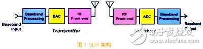
SDR architectureSDR is defined as a wireless communication system that uses software for wireless signal modulation and demodulation, which allows the application and reception of a wide range of signals. The transmit waveform is converted into a digital signal by software, and after digital-to-analog conversion and up-conversion, it is transmitted to the RF front-end and amplified; after the received waveform is amplified and down-converted to IF, it is digitized and demodulated by software (as shown in the figure). 1)). Compared to traditional designs, SDR has greater flexibility and lower cost.
The basic principle of SDR is to replace the analog circuit with a digital circuit controlled by software. In the SDR architecture, the following functions that should be implemented by analog circuits in the traditional sense are converted to digital hardware execution, including: frequency generation and conversion, modulation and demodulation, filtering, and I/Q detection. In addition, SDR includes unique digital features that improve radio performance, including interpolation and decimation methods that extend the dynamic range and waveform calibration of the radio to improve modulation accuracy by eliminating known analog distortion characteristics. The modulated signal is close to the waveform pre-correction of the ideal signal, and the like.
The means for implementing the above functions include: signal generating means, DAC, ADC and DDS; signal modulating means, DSP, DDC/DUC, FPGA, ASIC and general purpose processor (such as penTIums or powerPC).
Comparing the use of general purpose hardware and full software signal adjustment, from the system development and cost performance, the effect of software development is much better than the use of general purpose hardware. Driven by the communications industry, high-performance processing devices support more communication standards, making the SDR architecture more cost-effective.
The value and significance of SDR architectureCost trade-off
When the target customer needs to support a large number of different communication standards, the multi-functional SDR architecture is more cost-effective by using the same components; and for a single standard application, the traditional design is more advantageous.
flexibility
In terms of flexibility, the advantages of SDR are obvious. The performance is in two aspects: First, a single hardware can be designed to suit different communication standards, such as multi-standard cellular base stations, military communications. Second, SDR allows direct upgrades of new features, such as GSM to GPRS, IS95 to cdma2000 base stations.
Time to market
Because the SDR system has established a device for signal conditioning, it speeds time to market.
Model 2810/2910 new generation RF instrument
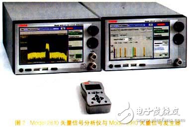
The Model 2810 Vector Signal Analyzer (shown on the left in Figure 2) and the Model 2910 Vector Signal Generator (shown on the right in Figure 2) are Keithley's next-generation RF instruments based on the SDR architecture, which use the same control and Software front panel.
Model 2810/2910 digital circuit structure
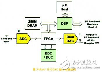
The Model 2810 vector signal analyzer and the Model 2910 vector signal generator use the digital circuit structure shown in Figure 3. The heavy signal adjustment in the design is done by DDC, DUC and DSP. The DSP selects the 500MHz device with the best price/performance ratio. The DDC and DUC are 16-bit 160MHz four-channel devices, each channel can be up-converted by software programming. Dynamic memory uses fast, high-capacity devices. The frequency of the IF signal input to the ADC is 100MHz to 200MHz, and the I/Q modulation is completed by the DSP. The DAC has two I/Q modulated outputs on the RF front end of the signal generator. In the design, the FPGA is mainly used to transmit signals and provide some real-time signals such as trigger signals, while the main processor is used to implement the user interface.
Model 2810/2910 software structure
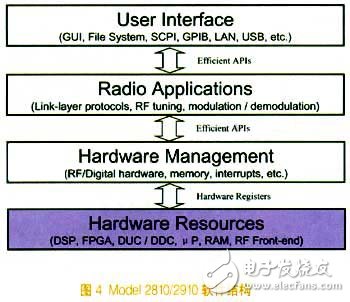
The Model 2810/2910 software architecture consists of three basic layers: the user interface layer, the radio application and the hardware management layer. User interface layer: It is run by the main CPU and is mainly responsible for the interaction between the user and the front panel or interface; the radio application and hardware management layer are completed by DSP coding, and the DSP has a dedicated internal programming environment. In software, the segmentation of two layers is achieved by coding, and the segmentation of the code is advantageous for improving the processing efficiency.
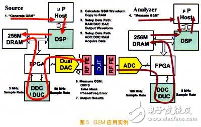
GSM application example
Figure 5 shows an example of GSM application. The specific steps of GSM signal generation and measurement are as follows: The main CPU accepts the command initiation, generates the GSM signal, and the command originates from the GUI or the remote control interface command. The data describing the waveform is contained in a small text file whose content is generated via the user interface or downloaded via the remote interface. Once the description is generated it will be stored as a file containing the active time slots and each time slot. data.
The data file is then transferred to the DSP. The DSP acquires the waveform description data according to the radio application layer, generates I/Q waveform data, and backs up the waveform into the DRAM. At the same time, the DSP sets the data path for the waveform data: the data will be transferred from the DRAM to the DUC to the DAC. . In this process, the FPGA is responsible for controlling the transmission of each time. At this point DUC is upconverted to 50MHz, and then the DAC is upconverted to 400MHz. These data are shaped by the signal filter at the RF front end, and finally the GSM output is to the RF front end.
DSP receiving part: First, the main CPU receives a GSM measurement command on the front panel or the remote control interface, and then the CPU sends a measurement command to the DSP, the DSP sets the data path, collects the measurement data, and implements down-conversion. At this point, data is transferred from the ADC to the DDC to the DRAM. Finally, the GSM measurement is completed by the DSP, including phase error and spectrum. All measurements are done using the same set of data, reducing measurement time.
Through the GSM application example, it is not difficult to find that two key advantages of using the SDR architecture are: First, it allows designers to change the price/performance ratio to meet customer needs, that is, to ensure performance levels at lower prices or to achieve performance improvements at the same price. . Secondly, the measurement time can be greatly improved, including: device settings and response time, instrument setup time, signal acquisition time and data processing time. Ideally, the customer's measurement time will only be limited by the DUT and not the measuring instrument.
The SDR architecture features high performance and low cost. As the industry advances, leading-edge digital devices based on this architecture will continue to evolve, and Keithley's flexible architecture will bring greater economic benefits to new applications.
Full Range Woofer,Magnet Woofer,Piezo Car Tweeter,Hi-Fi Dome Tweeter
NINGBO BOILINGSOUND ELECTRONICS CO.,LTD , https://www.tweeterspeaker.com