In fact, there is a very good article on the Internet that introduces the CRC algorithm. The author is Ross Williams and the title is "A PAINLESS GUIDE TO CRC ERROR DETECTION ALGORITHMS". Friends who read English without obstacles can also read the original text of Ross Williams.
The readership of this article is set up as a software developer, especially a programmer engaged in embedded software development, rather than a scholar specializing in mathematics or communication research. Therefore, the goal of this paper is to introduce the basic principles and implementation of the CRC algorithm. The mathematics used should be as close as possible to the depth that high school students can understand.
Speaking from parity
The so-called verification of the communication process refers to adding some additional information after the communication data, and using the additional information to determine whether the received data is the same as the transmitted data. For example, RS232 serial communication can set the parity bit. The so-called parity is to add one bit after each byte sent, so that the number of 1 in each byte is odd or even. For example, the byte we want to send is 0x1a, and the binary is 0001 1010.
With odd parity, the data is padded with a 0, the data becomes 0001 1010 0, and the number of 1 in the data is an odd number (3)
With even parity, the data is padded with a 1 and the data becomes 0001 1010. The number of 1s in the data is even (4).
The receiver determines whether the data is faulty by calculating whether 1 number in the data satisfies the parity. The shortcomings of parity are also obvious. First, its probability of detecting errors is only about 50%. That is, only half of the errors can be detected. In addition, one bit of parity is added for every byte transmitted, which has a great impact on transmission efficiency. Therefore, parity is rarely used in high-speed data communication. The parity advantage is also obvious, it is very simple, so it can be implemented in hardware, which can reduce the burden on the software. Therefore, parity is also widely used. Parity is introduced here first. The reason for the parity check is that this type of check is the simplest, and later it will be known that parity is actually a type of CRC check (CRC-1). .Accumulate and check
Another common way to verify is to add and verify. There are many ways to implement the summation and checksum. The most common one is to add one byte of parity data at the end of a communication packet. This byte is the byte-wise sum of the ignore carry of all the data in the previous packet. For example, the following example:
The information we want to transmit is: 6, 23, 4
Plus the checksum packet: 6, 23, 4, 33
Here 33 is the checksum of the first three bytes. After receiving all the data, the receiver performs the same cumulative calculation on the first three data. If the sum is the same as the last byte, the transmitted data is considered to be error-free. Accumulation and verification are very simple to implement and are widely used. However, the error detection capability of this type of verification method is also relatively general. For a single-byte checksum, there is a probability of 1/256, which misjudges the originally incorrect communication data as correct data. The reason why this check is introduced here is because the CRC check is the same as the accumulation check in the form of the transmitted data, and can be expressed as: the communication data check byte (may also be multiple bytes)First CRC algorithm
The basic idea of ​​the CRC algorithm is to treat the transmitted data as a long number of digits. Divide this number by another number. The resulting remainder is appended to the original data as check data. Take the data in the above example as an example:6, 23, 4 can be seen as a binary number: 0000011000010111 00000010
If the dividend is chosen 9, the binary representation is: 1001
Then the division operation can be expressed as:
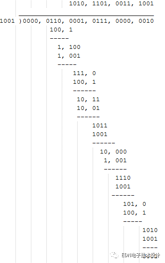
As you can see, the last remainder is 1. If we use this remainder as the checksum, the transmitted data is: 6, 23, 4, 1
The CRC algorithm is somewhat similar to this process, but it is not the usual division of the above example. In the CRC algorithm, the binary data stream is taken as the coefficient of the polynomial, and then the multiplication and division of the polynomial is performed. Let me give you an example. For example, we have two binary numbers: 1101 and 1011. 1101 is associated with the following polynomial: 1x3+1x2+0x1+1x0=x3+x2+x01011 is associated with the following polynomial: 1x3+0x2+1x1+ 1x0=x3+x1+x0Multiplication of two polynomials: (x3+x2+x0)(x3+x1+x0)=x6+x5+x4+x3+x3+x3+x2+x1+x0
After the results are obtained, the modulo 2 operation is used when merging similar items. That is to say, the multiplication and division method adopts the normal polynomial multiplication and division method, and the addition and subtraction methods all adopt the modulo-2 operation. The so-called modulo 2 operation is the result of dividing the result by 2 and taking the remainder. For example 3 mod 2 = 1. Therefore, the polynomial obtained above is: x6+x5+x4+x3+x2+x1+x0, corresponding binary number: 111111
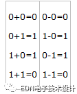
Addition and subtraction using modulo 2 operation actually becomes an operation, which is what we usually call XOR:
The above-mentioned half-day polynomial, in fact, even the concept of not introducing polynomial multiplication and division can also explain the special features of these operations. However, almost all polygraphs are mentioned in the literature explaining the CRC algorithm, so here is a simple basic concept. However, the use of this polynomial expression is also very arrogant, the following explanation will try to use a more concise way of writing.
The division operation is similar to the multiplication concept given above, and the XOR operation is replaced by the addition or subtraction. Below is an example:
The data to be transferred is
Divisor is set to: 10011
Fill in the original data with 4 zeros before the calculation. The reason is to make up 0, and then explain.
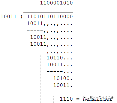
As can be seen from this example, after the addition and subtraction of the modulo 2, there is no need to consider the borrowing problem, so the division becomes simple. The resulting remainder is the CRC check word. In order to perform a CRC operation, that is, this special division operation, a dividend must be specified. In the CRC algorithm, the dividend has a proprietary name called "generating polynomial". The choice of generating polynomials is a very difficult problem. If the selection is not good, the probability of detecting errors will be much lower. Fortunately, this problem has been studied by experts for a long time. For those of us, just use the ready-made results.
The most commonly used generator polynomials are as follows: CRC8=X8+X5+X4+X0CRC-CCITT=X16+X12+X5+X0CRC16=X16+X15+X2+X0CRC12=X12+X11+X3+X2+X0CRC32=X32+X26 +X23+X22+X16+X12+X11+X10+X8+X7+X5+X4+X2+X1+X0One thing to note is that the generator polynomials mentioned in the literature often refer to the bit width (Width, abbreviated as W) of the polynomial. This bit width is not the number of bits of the binary number corresponding to the polynomial, but the number of bits minus one. For example, the generator polynomial with a bit width of 8 used in CRC8 actually has nine bits corresponding to the binary number:
100110001. In addition, polynomial representation and binary representation are cumbersome and inconvenient to communicate. Therefore, the literature uses hexadecimal shorthand to indicate that the highest bit of the generator polynomial is definitely 1, and the position of the highest bit is known by the bit width. In the shorthand, the highest 1 is removed. For example, the generator polynomial of CRC32 is abbreviated as 04C11DB7 and actually represents 104C11DB7. Of course, such a shorthand has its use in programming calculations in addition to convenience. For the above example, the bit width is 4 (W=4). According to the requirements of the CRC algorithm, W zeros, that is, four zeros, are added after the original data.There are two types of generator polynomial (CRC1) with a bit width W=1, which are X1 and X1+X0 respectively. The reader can prove that 10 corresponds to the odd parity in the parity, and 11 corresponds to the even parity.
Therefore, writing here we know that parity is actually a special case of CRC check, which is why I want to introduce parity as the beginning.Programming implementation of CRC algorithm
Having said that, it has finally reached the core. From the previous introduction, we know that the CRC check core is to implement the borrowing-free division operation. The following is an example to illustrate how to implement CRC check.
Suppose our generator polynomial is (abbreviated as 0x31), which is CRC-8.Then the calculation steps are as follows:
(1) Add the CRC register (8-bits, 1 bit less than the generator polynomial) to the initial value of 0 (2) Add 8 0 (3)While after the information stream to be transmitted (data is not processed) (4) Begin (5) If (the first bit of the CRC register is 1) (6) reg = reg XOR 0x31 (7) The CRC register is shifted one bit to the left, and a new data is read into the 0 bit position of the CRC register. (8) The End(9) CRC register is the remainder we require.In fact, the actual CRC calculations are usually somewhat different from those described above. This is because this most basic CRC division has a significant drawback, that is, adding 0 to the beginning of the data stream does not affect the result of the last check word. This problem is very annoying, so the real application of the CRC algorithm has basically made some minor changes based on the original CRC algorithm.
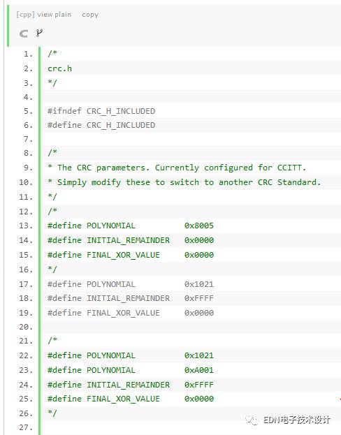
The so-called change, that is, the addition of two concepts, the first is the "residual initial value", and the second is the "result exclusive value".
The so-called "residual initial value" is the initial value of the CRC register at the beginning of the calculation of the CRC value. The "result exclusive value" is the XOR operation of the value of the CRC register as the last check value after the rest of the calculation is completed.
The common three CRC standards use the following parameters for each parameter.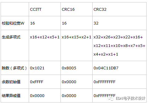
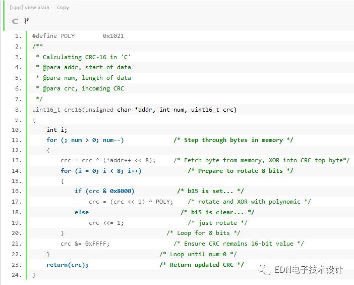
The above code was found by me from http://mdfs.net/Info/Comp/Comms/CRC16.htm, but the original code has errors and I made some minor changes.
The following gives an example fragment code for this function:
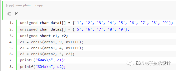
The reader can check that the results of c1 and c2 are both 29b1. The initial value of crc in the above code is 0xffff because the initial value of the divisor required by the CCITT standard is 0xffff.
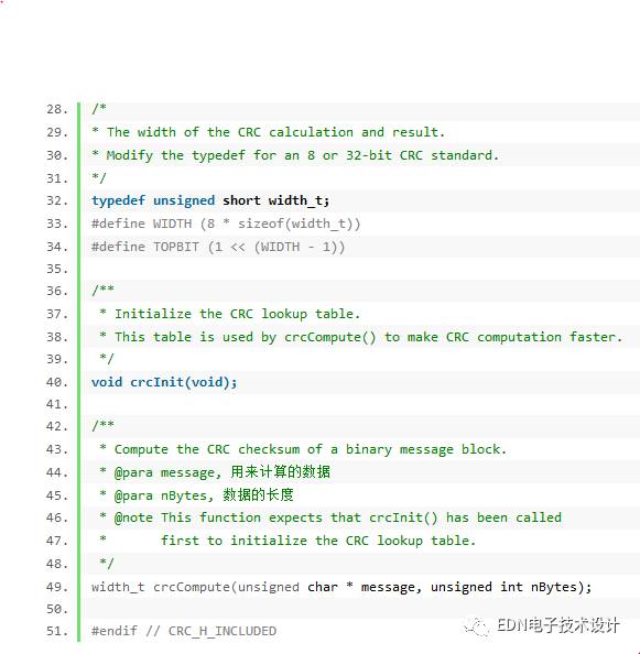
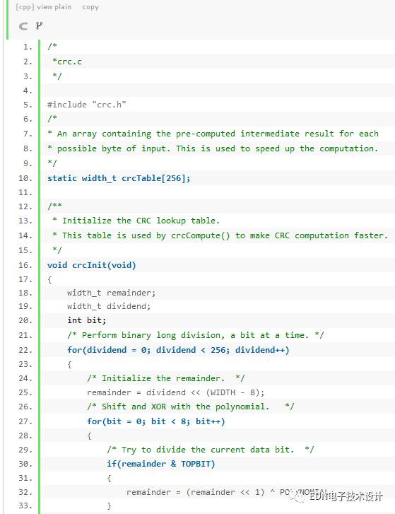
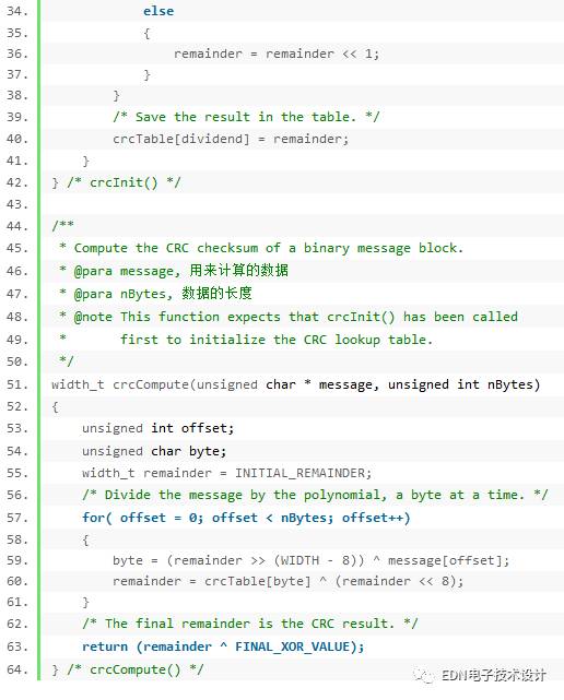
The above algorithm calculates the data stream bit by bit, which is inefficient. In fact, after careful analysis of the mathematical properties of the CRC calculation, we can calculate multiple bits and multiple bits. The most common one is a fast algorithm for looking up the table by byte. The algorithm is based on the fact that the CRC code after the calculation of this byte is equal to the lower 8 bits of the previous byte of the CRC code, shifted to the left by 8 bits, plus the previous byte CRC is shifted to the right by 8 bits and the byte. And the CRC code obtained afterwards. If we calculate the CRC (256 total) of the 8-bit binary sequence number and put it in a table, we only need to find the corresponding value from the table for processing.
According to this method, you can have the following code (this code is not written by me, I found it in Micbael Barr's book "Programming Embedded Systems in C and C++", and I made a small change.) :
Toolkits For Cutting Mahine and Cutting Materials
It is suitable for the blade of the Screen Protector Cutting Machine and the tools for installing the Screen Protection Film.
If you want to learn more about Accesseries For Cutter,Screen Protector Cleaning Tool, Cutting Blade, Cell Phone Scraper Tool, Tool Kit, Cutting Head Parts please click "Product Details" to view Accesseries For Cutter,Screen Protector Cleaning Tool, Cutting Blade, Cell Phone Scraper Tool, Tool Kit, Cutting Head Parts parameters, models, pictures, prices and other information .
Whether you are a group or an individual, we will try our best to provide you with accurate and comprehensive information about Accesseries For Cutter,Screen Protector Cleaning Tool, Cutting Blade, Cell Phone Scraper Tool, Tool Kit, Cutting Head Parts!Accesseries For Cutter,Screen Protector Cleaning Tool, Cutting Blade, Cell Phone Scraper Tool, Tool Kit, Cutting Head Parts
Shenzhen Jianjiantong Technology Co., Ltd. , https://www.jjthydrogelmachine.com