The liquid crystal display module has the advantages of small size, low power consumption, rich display content, ultra-thin and light weight, and has been widely used in pocket-type instruments and low-power application systems. Now the character-type liquid crystal display module is already a single-chip application. The most commonly used information display device in the design.
Introduction to LCD1602
Here to introduce the LCD1602 character type liquid crystal display module, it can display two lines, each line of 16 characters, equivalent to 32 LED digital tube, and more than the information displayed by the digital tube. It is powered by a single +5V power supply. The peripheral circuit configuration is simple, the price is cheap, and it has a high cost performance. The 1602 pin is shown in the figure below. The function of each pin is shown in the following table. The main pin functions are as follows:
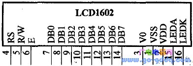
| Pin number | symbol | status | Features |
| 1 | Vss | Power ground | |
| 2 | Vdd | Power +5V | |
| 3 | V0 | LCD driver | |
| 4 | RS | enter | Register selection |
| 5 | R/W | enter | Read and write operations |
| 6 | E | enter | Enable signal |
| 7 | DB0 | Tristate | Data bus (LSB) |
| 8 | DB1 | Tristate | Data Bus |
| 9 | DB2 | Tristate | Data Bus |
| 10 | DB3 | Tristate | Data Bus |
| 11 | DB4 | Tristate | Data Bus |
| 12 | DB5 | Tristate | Data Bus |
| 13 | DB6 | Tristate | Data Bus |
| 14 | DB7 | Tristate | Data bus (MSB) |
| 15 | LEDA | enter | Backlight +5V |
| 16 | LEDK | enter | Backlit |
VO: LCD contrast adjustment end, the contrast of the positive power supply is the weakest; the contrast is highest when the grounding power supply. When the contrast is too high, "ghosting" will occur, and the contrast can be adjusted by a potentiometer of about 5k. RS: Register selection, select the data register when high level; select the instruction register when low level.
R/W: Read and write signal line, read operation when high level, write operation when low level. When RS and R/W are low together, the instruction or display address can be written; when Rs is high and R/W is low, data can be written.
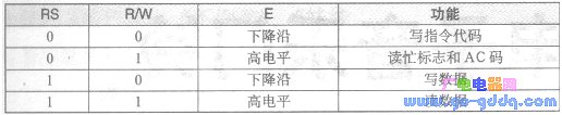
E: Enable terminal. When the E terminal changes from high level to low level, the liquid crystal module executes the command. The LCD1602 has 11 control commands, the functions of which are shown in the table below.
| instruction | Features |
| Clear screen | Clear DDRAM and AC values |
| reset | AC=0, cursor, screen back to HOME |
| Input mode setting | Set the cursor and screen movement mode |
| Display switch control | Set display, cursor and blinking on, off |
| Cursor, screen shift | Cursor, screen movement, does not affect DDRAM |
| Function setting | Working mode setting (initialization instruction) |
| CGRAM address setting | Set the CGRAM address. A5~A0=0~3FH |
| DDRAM address setting | DDRAM address setting |
| Read BF and AC values | Read busy flag BF value and address counter Ac value |
| Write data | Data is written into DDRAM or CGRAM |
| Reading data | Read from DDRRAM or CGRAM data |
Here are just a few instructions that are often used during programming:
1. Clear screen (see table below)
| RS R/W | DB7 DB6 DB5 DB4 DB3 DB2 DB1 DB0 |
| 0 0 | 0 0 0 0 0 0 0 1 |
2. Display switch control (see table below).
| RS R/W | DB7 DB6 DB5 DB4 DB3 DB2 DB1 DB0 |
| 0 0 | 0 0 0 0 1 DCB |
Function: Set display, cursor and blinking on and off.
Where: D indicates the display switch: D=1 is on, D=0 is off;
C indicates the cursor switch: C=1 is on, C=0 is off,
B indicates a flashing switch: B=1 is on and B=O is off.
3. cursor. Screen shift (see table below)
![]()
Function: Cursor, screen movement, does not affect DDR_AM.
Where: S/C=1: the picture is shifted by one character bit;
S/C=0: The cursor is shifted by one character bit;
R/L=1: right shift; R/L: O: left shift.
4 assist settings (see table below)
![]()
Function: Working mode setting (initialization command).
Where: DL=1, 8-bit data interface; DL=0, four-bit data interface;
N=1, two lines are displayed; N=0, one line is displayed;
F=1, 5×10 dot matrix characters; F=0, 5×7 dot matrix characters.
Read and write register
The control timing of the read and write registers is shown in the table below.
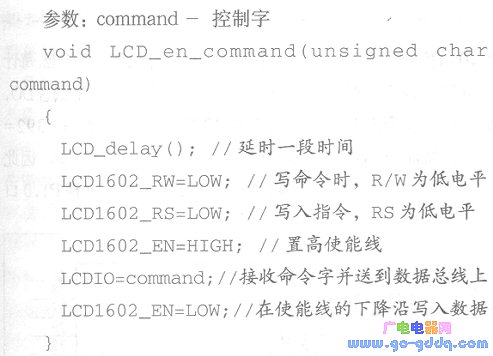
1. Write command function: write control word to register
Typical circuit
The typical circuit connections for the LCD1602 are shown below.
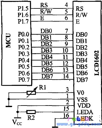
Description: Data line
DB0~DB7 are connected to the P0 port of the single-chip microcomputer; the three control lines are respectively connected to P1.5, P1.6, P1.7 (these control lines can be modified according to the specific hardware circuit), and the resistor R1 is used to adjust the liquid crystal display The contrast can be adjusted by a 5k potentiometer. The resistor R2 is used to set the brightness of the backlight. Generally, a 1k resistor can be used. Of course, the potentiometer can be connected to adjust the brightness of the display. Tip: Generally, in the circuit design, the liquid crystal is rarely directly implemented on the circuit board of the single chip microcomputer, but is transferred through an interface circuit, for example, a 16-line interface is left on the main board, so that a group of 16 can be passed. The root of the cable to connect the microcontroller and LCD.
driver
The drivers here mainly include:
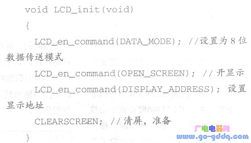
1. LCD initialization function: set the working mode of the LCD
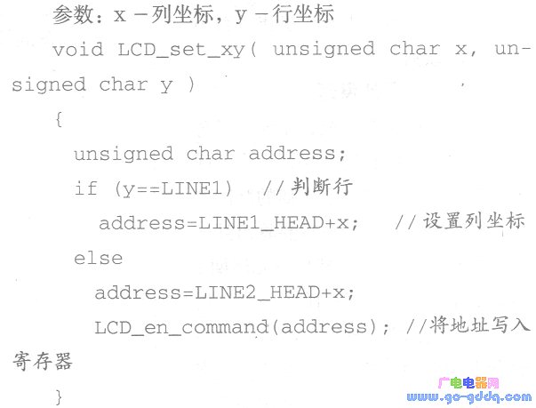
2. Set display coordinates: set the display position of characters, row and column coordinates
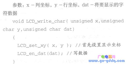
3. Write character function: write a character to the LCD
4. Write string function: write string to liquid crystal
Parameters: x-column coordinates, y-row coordinates, *s- characters to be displayed
data
Void LCD_write_string(unsigned char x,
Un8igned char y,unsi. Gned char*s)
{
LCD_set_xy(x,y);//First set the display coordinates
While(*s)//Check if it is over
{
LCDIO=*s;//Cycle call write data function
LCD_en_dat(*s);
8++:
}
}
A servo encoder slip ring is a specialized device that is used in conjunction with a servo motor to allow for the transfer of electrical power and signals between the motor and stationary components. The slip ring consists of a number of metal contacts that are arranged in a circular pattern, and it is typically mounted on the shaft of the motor. As the motor spins, the contacts within the slip ring make contact with corresponding contacts on the stationary components, allowing for the transfer of power and signals.
The primary benefit of using a servo encoder slip ring is that it prevents wear and tear on the electrical connectors that would otherwise be subjected to constant movement. Additionally, it can help to improve reliability and performance by providing a more consistent flow of power and signals.
It is specially developed for servo motor and servo motor encoder slip ring. It has the characteristics of small size, light weight, low power consumption, and long life. The inner diameter of the slip ring is only 10mm, which can be used in a small space. The service life of the slip ring is more than 100,000 hours, and the power consumption is only 0.5W.
A servo encoder slip ring is a device that allows an electrical current to pass between rotating and stationary parts of a machine. It does this by using a set of brush contacts that rotate with the shaft, while stationary contacts are mounted on the housing. This allows for uninterrupted power and data transmission in applications where the stationary component cannot be easily moved.
Oubaibo is a leading manufacturer and supplier of servo encoder slip rings. They produce high-quality products that are reliable and durable, and they specialize in slip ring 18 wire, and commutators. Their products are used in a variety of industries, including aerospace, defense, medical, and manufacturing.
Servo Encoder Slip Ring,Slip Ring Korea,Slip Ring 18 Wire,Commutator With Slip Ring
Dongguan Oubaibo Technology Co., Ltd. , https://www.sliproubos.com