What are the main applications of charge pumps?
In the past decade, charge pumps have been widely used, ranging from single-output ICs to adjustment ICs with multiple output voltages. Output power and efficiency have also evolved, so today's charge pumps can deliver up to 250mA with an efficiency of 75% (average). Charge pumps are mostly used in systems that require batteries, such as cellular phones, pagers, Bluetooth systems, and portable electronic devices.
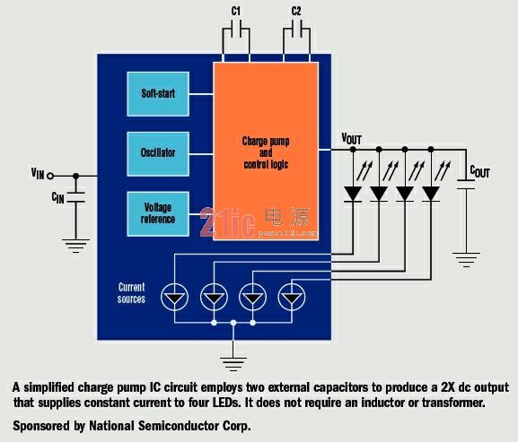
Key applications include driving white LEDs for cell phone backlights and digital processors in the milliwatt range (pictured).
How does the charge pump work?
A charge pump (switched capacitor) IC performs DC/DC voltage conversion by powering or de-energizing two or more capacitors using a single switching network. The basic charge pump switch network constantly switches between the two states of powering and powering down the capacitor. C1 (charging capacitor) transfers charge, while C2 (charging capacitor) stores charge and filters the output voltage.
Additional "fast capacitance" and switch arrays offer a number of benefits.
What are the operating modes of the charge pump?
The charge pump IC can be used as an inverter, splitter or booster. The inverter converts the input voltage into a negative output. When used as a splitter, the output voltage is part of the output voltage, such as 1/2 or 2/3. As a supercharger, it can bring a 1.5X or 2X gain to the I/O. Many portable systems use a single lithium ion battery or two metal hydride nickel batteries. Therefore, when operating in 2X mode, the charge pump can supply a suitable forward voltage to a white LED that typically operates in the range of 3.3V to 4.0V.
Is the output voltage of the charge pump adjusted?
The basic charge pump lacks an adjustment circuit, so virtually all current charge pump ICs use linear regulation or charge pump modulation. Linearly adjusted output has the lowest noise and provides better performance at lower efficiency. Since the trim IC does not have a series transfer transistor, the charge pump modulation that controls the switch resistance provides higher efficiency and provides more output current for a given chip area (or consumption).
What are the main advantages of the charge pump?
The charge pump eliminates the magnetic fields and electromagnetic interference that the inductor and transformer carry. However, there is still a possible source of small noise, which is the high charging current flowing to a fast capacitor when it is connected to an input source or another capacitor with a different voltage. Similarly, the "splitter" charge pump can also improve efficiency on LDOs, but not as complex as inductive buck regulators.
Is the output voltage of the charge pump compatible with its input voltage?
The charge pump can continuously change its output voltage depending on the battery voltage input. For example, it can run in either 1.5X or 1X mode. When the input voltage of the battery is low, the charge pump can generate an output voltage equivalent to 1.5 times the input voltage. When the battery voltage is high, the charge pump operates in 1X mode, at which point the load charge pump simply transfers the input voltage to the load. This reduces input current and power loss when the input voltage is high.
What happens to the switching frequency of the capacitor?
Increasing the switching frequency also increases the quiescent current of the IC, but it also reduces the capacitance of C1 and C2. The normal frequency structure provides low noise to regulate the output voltage while the input noise is lower than conventional charge pump regulators. High frequency operation simplifies filtration, further reducing conducted noise.
Which capacitors are best for a charge pump?
To achieve optimal performance, capacitors with low equivalent parallel resistance (ESR) are used. Low ESR capacitors must be used on the output of the IC to minimize output ripple and output resistance for maximum efficiency. Ceramic capacitors can do this, but some tantalum capacitors may be a little more appropriate.
What effect will the charge pump soft start have?
Soft-start can prevent excessive current flow at VIN at startup, increasing the amount of current that can be periodically used to output a charge storage capacitor. Soft-start is typically activated when the device is turned off and masked as soon as the device is adjusted.
How does the charge pump IC minimize power consumption?
By using pulse frequency modulation, the IC generates charge only when the charge must be transmitted to maintain output regulation. When the output voltage is higher than the target regulation voltage, the IC is idle, and the current consumed is minimal because the charge stored on the output capacitor provides the load current. As the capacitor continues to discharge and the output voltage gradually drops to the target regulation voltage, the charge pump activates and transfers charge to the output. This charge supplies the load current and increases the voltage across the output capacitor.
This website tries to open micro- and small-enterprise business advertising business; maintenance point recommended items. The fee is affordable and effective! Welcome to contact in QQ or email!
Why do you want to do online advertising contact?
- 0
- like
| Try to find the information you want to see. Inverter sensor patch three no weight loss camera LCD monitor does not boot digital camera XC9237 projector switching power supply laptop processor IPSUSB skills entrepreneurial black screen water heater can not boot circuit design silent transformer XC6102 without sound XC6112 display regulator no image microwave player successful silent GPS tea no picture XC6222 health XC6372 relay filter ML6209 switch washing machine digital camera description remote control without grating 555 protection circuit cancer self-closing Linux charger mobile phone shutdown noise inverter oscilloscope robot Windows antenna indicator light is not bright fiber life transformer stomach market alarm Hard disk watch embedded system woman maintenance process memory XC9236 converter router interview server kidney RFIDLED driver Konka CDMA instrument Panasonic CCD flashing engine multimeter Apple liver motor resistance keyboard integrated circuit current transformer triode governor power supply LED |

What is a Capsule Slip Ring?
Capsule slip rings are a type of electrical connector that are used to transfer power and data between two rotating objects. They are commonly used in applications where there is a need to send or receive signals from a stationary object to a rotating one, or vice versa.
How Does it Work?
Capsule slip rings work by using a series of electrical contacts that rotate with the object on which they are mounted. These contacts are spaced evenly around the circumference of the ring, and as they rotate they make and break contact with corresponding contacts on the other object. This allows power and data to be transferred between the two objects without any interruption.
Advantages of Capsule Slip Rings
There are several advantages to using capsule slip rings in place of other types of electrical connectors.
For example, the rotation of the contacts causes them to be freely accessible and therefore free from dust and debris. This makes them ideal for applications where connector maintenance is often a problem.
Because the contacts are freely accessible, they can be readily replaced if a fault occurs. They also have very low electrical resistance, making them ideal for transmitting radio frequency signals. Because of the low resistance, this type of connector is often used in high-speed data transmissions.
This type of Conductive Slip Ring is similar to the shape of a hat. The brim part is a flange with a conductive slip ring. The function of the flange is to facilitate installation. It is connected to electrical equipment through the fixing hole of the flange. It can be firmly installed on the equipment. Therefore, the stator of the cap-type slip ring is generally fixed by the outer layer with a flange, and the inner part is the rotor with the inner shaft rotating. The stator and the rotor are not fixed, and the details will be different according to the installation method.

Capsule Slip Ring,Split Ring Motor,Slip Ring Motor Connection,Slip Rings In Synchronous Motor
Dongguan Oubaibo Technology Co., Ltd. , https://www.sliprobs.com